

PREFACE
This kit provides AC lighting for 1995 (EO) and newer 4-stroke 9.9/15 (305 cc) or 3 cylinder 25/35 models. The stator used in this kit also services original stator on these models.
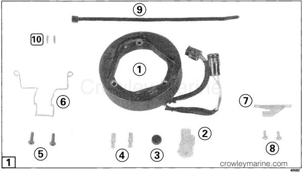
[1]
Read instructions prior to starting work. Check contents of kit:
9.9/15 HP
| Ref. | Name of Part | Qty. |
|---|---|---|
| 1 | Stator Assembly | 1 |
| 2 | Connector Receptacle | 1 |
| 3 | Connector Seal Plug | 1 |
| 4 | Blade Terminal | 2 |
| 5 | Connector Retaining Screw | 2 |
| 6 | Connector Retainer | 1 |
| 7 | NOT USED | - |
| 8 | NOT USED | - |
| 9 | Tie Strap | 1 |
| 10 | Seal Plug | 2 |
9.9/15 HP
| Ref. | Name of Part | Qty. |
|---|---|---|
| 1 | Stator Assembly | 1 |
| 2 | Connector Receptacle | 1 |
| 3 | Connector Seal Plug | 1 |
| 4 | Blade Terminal | 2 |
| 5 | NOT USED | - |
| 6 | NOT USED | - |
| 7 | Connector Bracket | 1 |
| 8 | Connector Bracket Screw | 2 |
| 9 | NOT USED | - |
| 10 | Seal Plug | 2 |
To avoid accidental starting of engine, twist and remove all spark plug leads.
Remove manual starter and flywheel. Refer to Section 3 in the Service Manual.
Stator Service Only - All Models
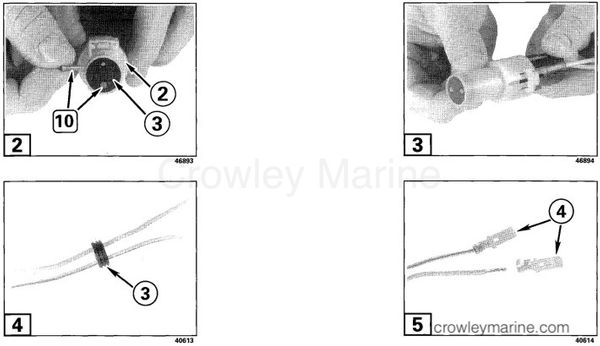
[2]
Insert connector seal plug (3) into connector receptacle (2). Insert one seal plug (10) into each hole in connector seal plug.
[3]
Snap connector receptacle onto AC lead plug. Go to applicable AC installation instruction to complete.
AC Installation - All Models
[4]
Select two pieces of 18 gauge wire of length necessary for use. Wire colors should be yellow and yellow/gray to match leads on stator. Insert wires into connector seal plug (3).
[5]
Strip wire ends and install blade terminals (4) on ends.
[6]
Push terminals into the connector receptacle (2) until they snap into place.
[7]
Push seal plug into the connector until seated.
9.9/15 Models
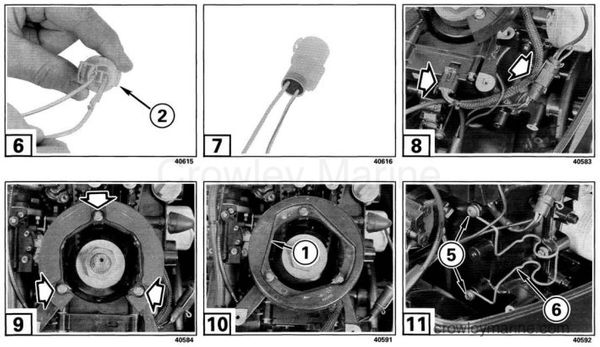
[8]
Disconnect the stator wire connector from the ignition module, and remove the tie strap retaining the oil pressure sender connector to the braided sleeve.
[9]
Remove the screws and star washers retaining the stator; remove stator.
[10]
Place new stator assembly (1) in position. Apply Nut Lock to screw threads, insert with star washer, and torque to 120-144 in. lbs. (14-16 Nm).
[11]
Install connector retainer (6) in position on powerhead. Lubricate threads with engine oil and install connector retainer screws (5). Torque to 108-132 in. lbs. (12-15 Nm).
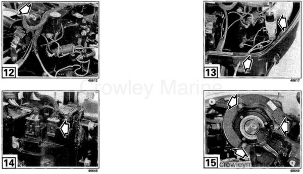
[12]
Route stator wires, as shown. Snap ignition module connector in place, and tie strap oil pressure sender connector to retainer.
[13]
Snap AC connector together and place in retainer. Cut a slit in the lower cover grommet if routing wire to boat.
25/35 Models
[14]
Disconnect the stator wire connector from the ignition module.
[15]
Remove the screws retaining the stator; remove stator.
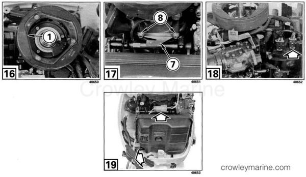
[16]
Apply Nut Lock to screw threads, place new stator assembly (1) in position, and torque to 120-144 in. lbs. (14-16 Nm).
[17]
Install connector bracket (7) in position on powerhead. Apply Nut Lock to threads of connector bracket screws (8) and torque to 96-107 in. lbs. (10-12 Nm).
[18]
Route stator wires, as shown, and snap ignition module connector in place.
[19]
Snap AC connector together and place in bracket. Cut a slit in lower cover grommet if routing wire to boat.
If operating outboard with AC lighting disconnected, secure wire terminals to prevent them from shorting together or shorting to a metal boat. Keep terminals dry.
All Models
OPERATION:
Install the flywheel and manual starter. Refer to Section 3in the service manual for installation.
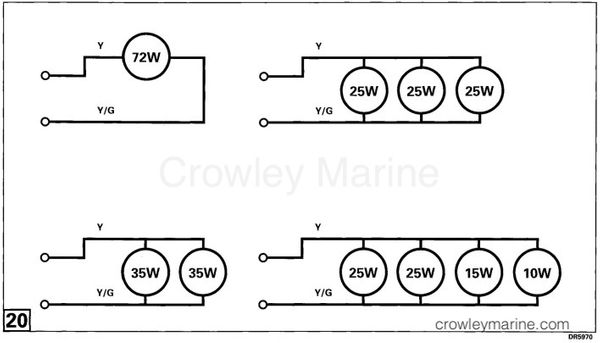
[20]
Each bulb must be connected to the yellow and yellow/gray wires.
Bulb Selection: Use any of the bulb wattage combinations shown. Do not use more than 80 watts or the lights will be dim. Do not use less than 70 watts or the bulbs will burn out.
Note: This wiring must not be connected to a battery or the electrical system will be damaged.
0584861 - AC Lighting Kits
0176278 - Johnson/Evinrude, OMC A/C Light Kit 6A