

ELECTRONIC FUEL INJECTION SYSTEM
The fuel injection system used by the DF60/DF70 is a speed-density, multi-point, sequential, electronic fuel injection type.
The fuel injection system is composed of the fuel line components, air intake components, and components for system control (ECM, sensors, switches, etc.).
FUEL INJECTION CONTROL SYSTEM
OUTLINE
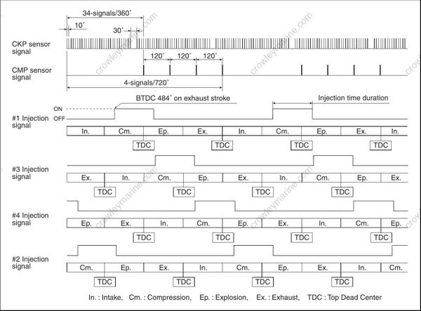
The sensors are mounted at precise locations on the motor to monitor the current conditions of engine operation and send signals to the ECM. Based on these signals, the ECM determines the optimum fuel injection time duration (fuel amount), fuel injection timing (multi-point sequential timing) and controls the injector operating signals accordingly. Fuel injection start timing is set at BTDC 484° on exhaust stroke constant.

FUEL INJECTION TIMING CHART
The fuel injection timing is always fixed at BTDC 484° on exhaust stroke.
The fuel ignition time duration (amount) is varied by the condition of the engine running.
Angles indicated in the following chart show the CRANKSHAFT angle.
CONTROL MODE
BEFORE START:
When the ignition switch is turned “ON”, the ECM receives a MAP sensor signal, indicating the static barometric pressure of the intake manifold, which is used to compensate the fuel injection map for altitude.
WHEN CRANKING:
Fuel is simultaneously injected to all cylinders every time any piston is positioned at compression stroke. AFTER START (FAST-IDLE FUNCTION):
The fuel injection amount is controlled to increase until the timer, set according to cylinder temperature at the time of engine start, expires.
WHEN IDLING/TROLLING:
The fuel injection amount is controlled to maintain a stable engine speed at the specified idle/trolling rpm.
WHEN ACCELERATING:
The fuel injection amount is controlled to increase.
WHEN DECELERATING:
The fuel injection amount is controlled to decrease.
The fuel injection is also cut off on very rapid engine deceleration.
FUEL DELIVERY SYSTEM COMPONENTS
The fuel delivery system is composed of the low pressure line components (fuel tank, filter, pump etc.), fuel vapor separator, high pressure fuel pump, high pressure fuel filter, fuel pressure regulator (located in the fuel vapor separator), delivery pipe, fuel injector and hoses.
Fuel is supplied through the primer bulb, low pressure fuel filter, and low pressure pump to the fuel vapor separator.
Fuel flow from the fuel vapor separator is pressurized by the high pressure fuel pump and supplied through the high pressure fuel filter and fuel delivery pipe to the fuel injectors.
The pressure regulator maintains fuel pressure in the feed line between the high pressure fuel pump and fuel injector.
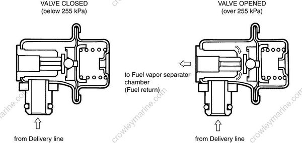
This pressure, maintained at a constant level, is higher than the pressure in the vapor separator chamber. When the fuel feed line pressure exceeds the vapor separator chamber pressure by more than approx. 255 kPa (2.55 kg/cm2, 36.3 psi), the valve in the fuel pressure regulator will open and return the excess fuel to the vapor separator chamber.
Pressurized fuel enters into the intake ports through the fuel injector based on the sequential signals sup plied from the ECM.

FUEL VAPOR SEPARATOR
The fuel vapor separator incorporates a float system that maintains a constant fuel level inside the separator chamber.
As the fuel level decreases, fuel flows into the vapor separator from the low pressure fuel pump.
The function of this unit is to separate vapors from fuel delivered by the low pressure fuel pump or fuel returned from the fuel pressure regulator.
This vapor is routed through the evaporation hose connecting the vapor separator cover to the silencer cover.
HIGH PRESSURE FUEL PUMP
The high pressure fuel pump is an “integral” type in which the pump mechanism is located within the fuel vapor separator.
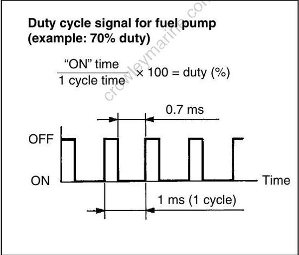
To supply the optimum fuel amount, the pump is driven by the duty cycle signal from the ECM.

FUEL PRESSURE REGULATOR
The fuel pressure regulator is located in the fuel vapor separator.
The regulator’s function in the system is to maintain a constant fuel pressure relative to the injector while the engine is operating.
The regulator diaphragm chamber is open to the vapor separator chamber to keep the pressure balanced. Fuel pressure, adjusted by the regulator, is constantly maintained higher than the pressure in the fuel vapor separator chamber by approx. 255 kPa (2.55 kg/cm2, 36.3 psi).
By-pass fuel is returned back to the fuel vapor separator chamber.
FUEL INJECTOR
The fuel injector is an electromagnetic valve operated by a signal from the ECM.
When the injection signal is supplied to the fuel injector, the solenoid coil is energized pulling up the plunger. This opens the injector valve and injects fuel.
Because the fuel pressure is kept constant, the amount of fuel injected is determined by the amount of time (duration) the valve is open.

FUEL PUMP CONTROL SYSTEM
OUTLINE
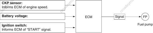
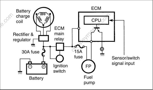
To supply the optimum fuel amount, the ECM controls the fuel pump drive duty cycle, a repeated ON/OFF signal, at a specified rate (1 000 times a second).
Based on engine speed and battery voltage, the ECM determines the optimum duty (repeating “ON” time rate within a cycle) and sends this signal to the fuel pump.
CONTROL MODE
BEFORE START:
For 3 seconds after ignition switch is turned “ON”, the pump is controlled to operate at 100% duty in order to initially pressurize the high pressure line.
WHEN CRANKING:
The pump is controlled to operate at 100% duty.
WHEN RUNNING (NORMAL OPERATION):
The pump is controlled to operate at 60 – 100% duty based on the current engine speed and battery volt age.
AIR INTAKE COMPONENTS
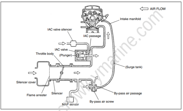
Air, after entering through the silencer, passes through the throttle body and flows into the surge tank where it is then distributed to the cylinder intake manifold.
Intake manifold pressure, monitored by the MAP sensor, is an indirect measure of the intake air amount.
When the throttle is fully closed, the main supply of intake manifold air necessary to sustain the engine idle passes through the by-pass air passage.
To maintain the engine idle speed at the specification, the ECM controlled the IAC valve supplies a regulated amount of additional air through the IAC (idle air control) passage.
THROTTLE BODY
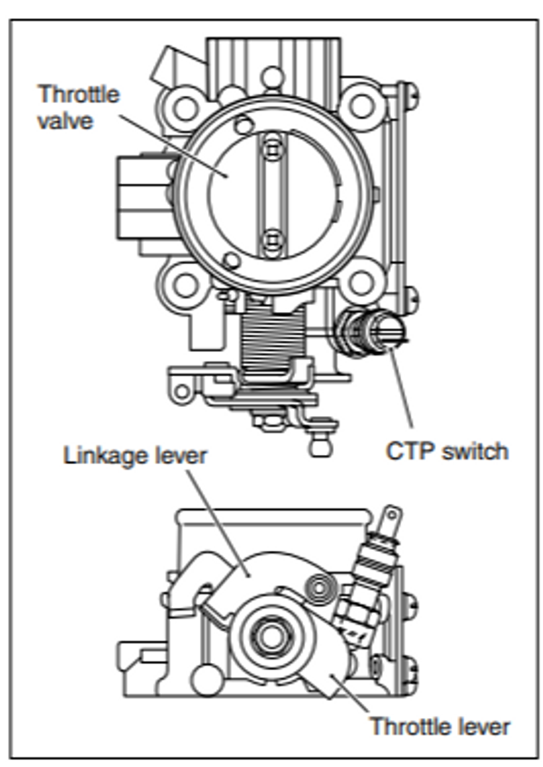
The throttle body adjusts the intake air amount with the throttle valve which is connected to the throttle/linkage lever. The CTP (closed throttle position) switch is installed on the bottom of the throttle body. The CTP switch informs of a throttle valve position.
Do not try to adjust or remove any of the throttle body component parts (CTP switch, throttle valve, throttle/linkage lever, etc.).
These components have been factory adjusted to precise specifications
BY-PASS AIR SCREW/PASSAGE
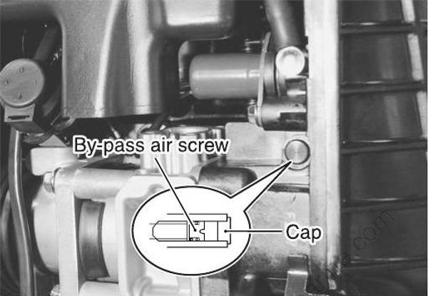
Since the throttle valve is almost fully closed when idling/trolling, the main flow of air necessary to maintain idling/trolling speed passes through the by-pass air passage.
The by-pass air screw controls the flow of air through the pas sage and provides a means of partially adjusting the total amount of air necessary for idling/trolling.
See the page 2-14 for the by-pass air screw adjustment procedure.
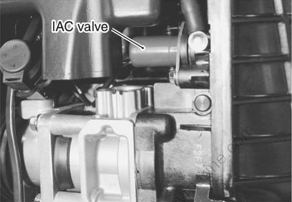
IAC VALVE/PASSAGE
The IAC valve is a linear solenoid plunger type mounted on the intake manifold (surge tank).
Its purpose is to control the amount of intake air flowing from the IAC passage.
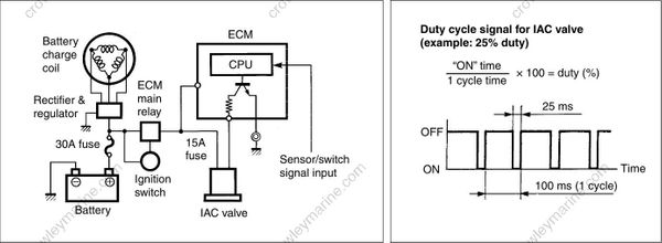
The IAC valve is driven by the duty cycle signal from the ECM.
IDLE AIR CONTROL SYSTEM
OUTLINE
The ECM controls the duty cycle signal of the IAC valve to regulate a portion of the intake air flow to the intake manifold.
This system is used for the following purposes:
To keep idling/trolling at the specified speed.
To improve drive ability when decelerating (Dash-pot effect).
To improve engine starting and warm-up performance (Fast-idle function).
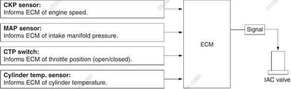
The sensors/switch shown below monitor current engine condition and send signals to the ECM. Based on these signals, the ECM determines the optimum duty cycle (repeating “ON” time rate within a cycle). A repeating ON/OFF signal at a specified rate (10 times a second) is then sent to the IAC valve.
CONTROL MODE
BEFORE START:
The IAC valve is closed (0% duty) when engine is not running.
WHEN CRANKING:
The IAC valve is controlled to operate at 100% duty.
AFTER START (FAST-IDLE FUNCTION):
The IAC valve is controlled to operate at approx. 25 – 100% duty until the timer, which was set according to cylinder temperature at cranking, expires.
WHEN IDLING/TROLLING:
The IAC valve is controlled so that the engine speed is stable at the idling/trolling speed specified.
During this period, the IAC valve has a duty cycle of approx. 22.5% but will vary slightly as idling/trolling conditions change.
WHEN RUNNING (NORMAL OPERATION):
The IAC valve is controlled to operate at 20 – 100% duty, which depends on the current engine conditions. WHEN DECELERATING (DASH-POT EFFECT):
When the throttle valve is suddenly returned to full close and the CTP switch signal changes to “ON”, the IAC valve operates at a controlled gradual return to idle/troll operating duty to prevent engine stalling or unstable running.
Due to the limited intake air flow from the IAC passage and in order to effectively use both the “Dash-pot effect” and “Fast-idle function”, the by-pass air screw must be adjusted to provide IAC valve operation at approx. 22.5% duty at the engine idling/trolling specification.
See the page 2-14 for the by-pass air screw adjustment procedure.
