

SENSOR AND SWITCH
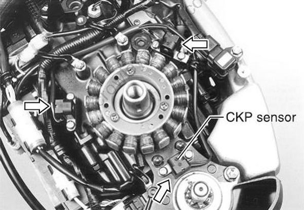
CKP (Crankshaft Position) SENSOR
There are three (3) CKP sensors installed below the flywheel rotor.
When the reluctor bar on the flywheel passes the sensors, a signal (voltage pulse) is generated and sent to the ECM.
This is the fundamental signal used to judge the engine speed and crankshaft angle.
CMP (Camshaft Position) SENSOR
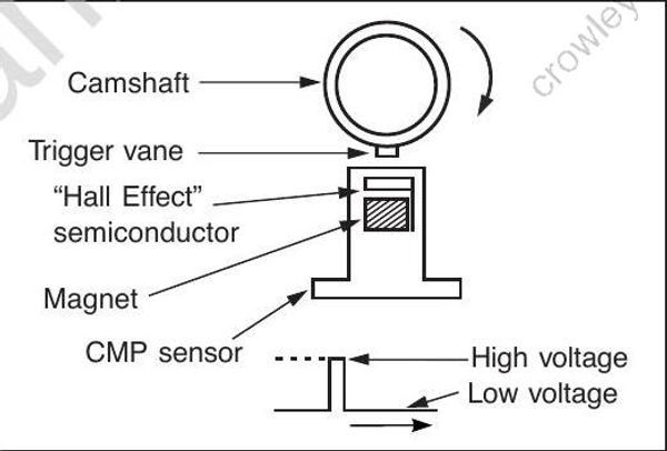
A CMP sensor mounted on the cylinder head cover and a reluctor bar pressed onto the end of the intake camshaft are used to detect piston position. The signal from this sensor is received by the ECM which uses it to determine sequential fuel injection control.

The CMP sensor contains a “Hall Effect” semiconductor and a magnet. The semiconductor generates a voltage in proportion to the line of magnetic force passed through it. When the single trigger vane on the camshaft reluctor aligns with the sensor’ internal magnet, a large amount of magnetic force is generated allowing a high voltage to pass through the semiconductor. When the trigger vane moves away from the sensor, no magnetic force is generated and low voltage passes through the semiconductor.
These generated voltages are rectified to create “ON” (high voltage) & “OFF” (low voltage) signals for ECM. The “ON” volt age signal indicates the position of #1 piston. The position of #2 and #3 pistons, “OFF” signal, follow in firing sequence order based on the now established position of #1 piston.
CYLINDER TEMPERATURE SENSOR
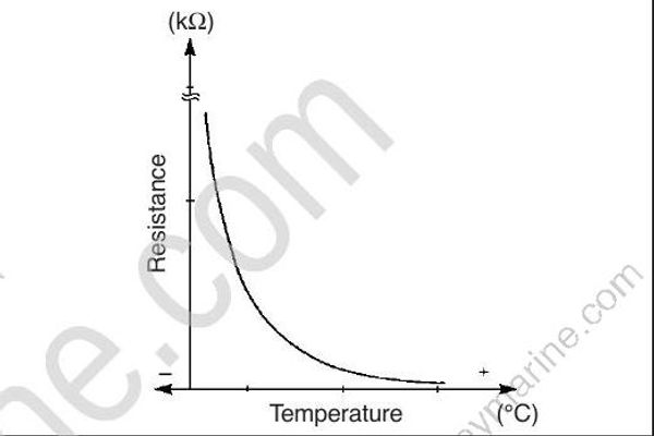
The cylinder temperature sensor is installed on the cylinder (top side) and used to detect the cylinder temperature.
This is a thermistor type sensor (resistance of which changes depending on the temperature) and inputs a signal to the ECM as a voltage value. This input signal is used to compensate the fuel injection time duration, ignition timing, etc.
This sensor is also used to detect engine over-heat as the ECM detects both the temperature and temperature change gradient (temperature rise Vs time).

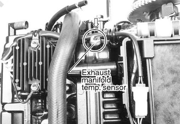
EXHAUST MANIFOLD TEMPERATURE SENSOR
The exhaust manifold temperature sensor is installed on the exhaust manifold and used to detect the exhaust manifold tem perature. This sensor is the same type as the cylinder temperature sensor, and inputs a signal to the ECM as a voltage value. This input signal is used to detect engine over-heat.
IAT (Intake Air Temperature) SENSOR
The IAT sensor is installed on the bottom of the air silencer and used to detect the intake air temperature.
This sensor is the same type as the cylinder temperature sensor, and inputs a signal to the ECM as a voltage value.
This input signal is used to compensate the fuel injection time duration.

MAP (Manifold Absolute Pressure) SENSOR
The MAP sensor is installed on the intake manifold and used to detect the intake manifold pressure. It also detects the baro metric pressure before starting the engine. This sensor inputs the intake manifold pressure to the ECM as a voltage value. This input signal is used as the fundamental signal to deter mine the fuel injection time duration, ignition timing, etc.

CTP (Closed Throttle Position) SWITCH
The CTP switch is installed on the top of throttle body and used to detect whether the throttle is fully closed or not.
This switch inputs the signal to the ECM. The ECM detects the throttle position and determines the control modes for various control system (idle air control, ignition timing control, etc.).

NEUTRAL SWITCH
The neutral switch is installed on the cylinder block (PORT side) and used to detect the shift position.
This switch is “ON” in neutral and “OFF” in forward or reverse. The ECM detects shift position and performs the following controls :
Fuel injection is not performed when the shift is in forward or reverse at the time of engine start.
(Start-in-gear protection. See page 3-31)When the shift is in neutral, fuel injection is controlled so that the engine speed does not exceed 3000 r/min.
When the shift is in neutral, if the engine speed exceeds 1200 r/min, the ignition timing is fixed at BTDC 9°.
For two seconds after shifting into forward or reverse from neutral, the IAC valve is controlled so that intake air increases to prevent unstable engine idle or stalling.

ECM MAIN RELAY
The ECM main relay is installed in the electric parts holder.
When energized by the turning ignition switch ON, it forms the circuit which supplies battery voltage to the ECM, injector, ignition coil, IAC valve, CMP sensor and high pressure fuel pump.

O₂ SENSOR (Optional item)
The O₂ sensor is installed in the exhaust manifold only when the O₂ feedback operation is performed.
This sensor is a zirconia element (platinum plated) the output voltage of which changes depending on the oxygen concentration. The voltage change reflects the concentration of the oxygen in the exhaust gas and is used to perform the O₂ feedback operation.
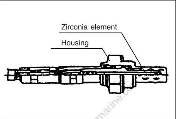
The terminal voltage change (0 – 1 V) is dependent on the concentration of oxygen in the exhaust gas.
This detected voltage value therefore represents the oxygen concentration. The terminal voltage decreases when the oxygen concentration is high, and increases when it is low.
As the zirconia element is not conductive below 250°C, the O₂ sensor will not function properly until the engine is at normal operating temperature.
Zirconia element
The zirconia element produces a potential difference (voltage) when there is a difference in the oxygen concentration of the gases which contact the two sides of the element.
Since the inner surface of the zirconia element (inside the sensor) is exposed to atmospheric air and the outer surface exposed to the exhaust gas, there is a difference in oxygen concentration on each side and thus a difference in the potential generated.
