

REASSEMBLY
Assembly is reverse order of disassembly paying special attention to the following steps.
If original components are not replaced, each piston, piston pin and conrod is to be assembled and installed in its original order and position.
PISTON TO CONROD
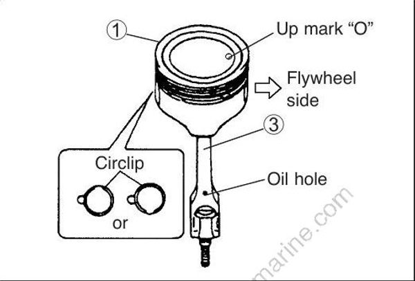
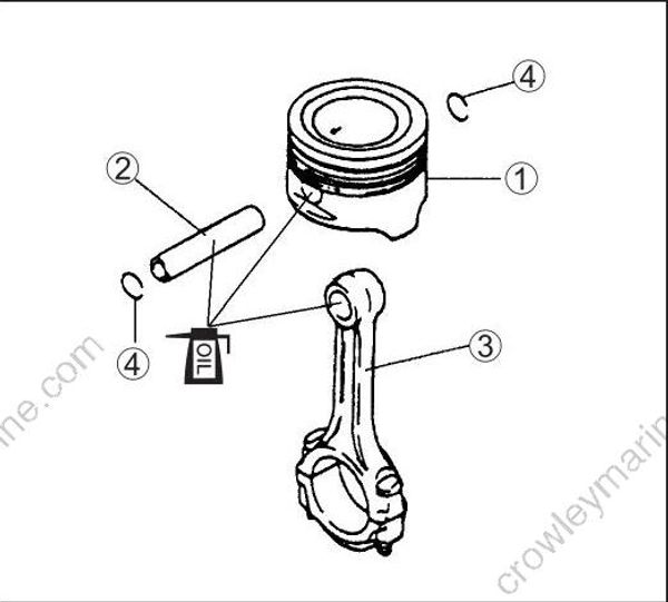
Apply engine oil to piston pin (2), piston pin bore and conrod (3). Fit conrod (3) to piston (1) as shown in figure and insert piston pin 2 through piston and conrod. Install piston pin circlips (4).
• Make sure conrod is installed in the direction shown.
• Circlip should be installed with gap facing either up or down as shown in figure.
• Always use new piston pin circlip.
PISTON RING TO PISTON
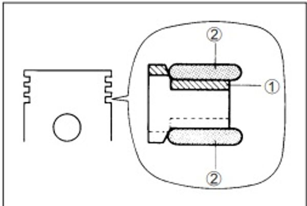
Oil ring
- Apply engine oil to piston rings.
- Install spacer 1 first, then side rails 2 to piston.
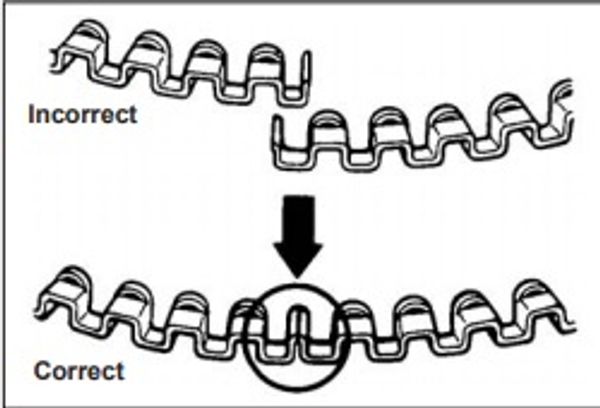
When installing spacer, do not allow ends to overlap in groove.
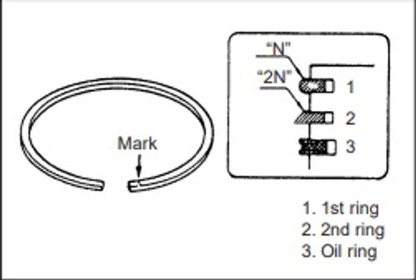
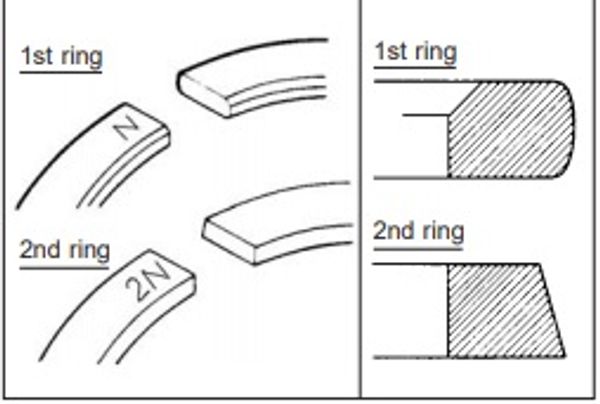
1st ring and 2nd ring
- Apply engine oil to piston ring.
- Install 2nd ring and 1st ring to piston.
• 1st ring differs from 2nd ring in shape and color of surface contacting cylinder wall.
Distinguish 1st ring from 2nd ring by referring to figure.
• As indicated in figure, 1st and 2nd ring are marked, “N” or “2N” .
When installing these piston rings, the marked side of each ring must face towards top of piston.
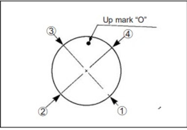
Ring gap direction
Position rings so that their gaps are staggered at approximately 90 degree angles as shown.
(1) 1st ring
(2) Oil ring lower side rail
(3) 2nd ring
(4) Oil ring upper side rail
Failure to stagger piston ring gaps may result in crankcase oil dilution.
PISTON TO CYLINDER
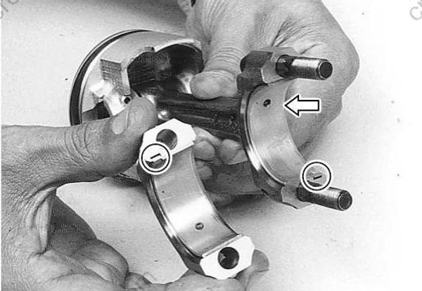
Install conrod bearing to conrod and conrod cap
• Assemble each conrod bearing to its original position.
• Do not apply oil between conrod and bearing or between bearing cap and bearing.
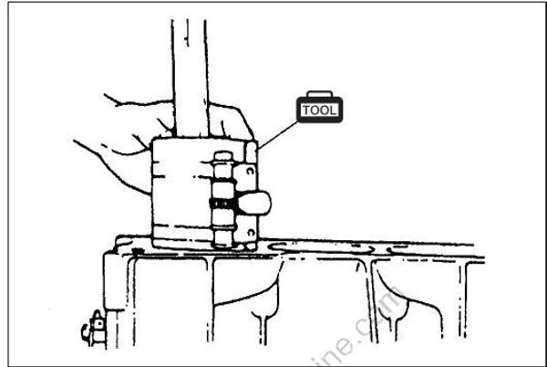
Apply engine oil to piston and cylinder walls.
Insert piston and conrod assembly into cylinder bore from cylinder head side using special tool
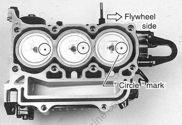
Position the “circle” mark on piston head to flywheel side.
CRANKSHAFT TO CYLINDER
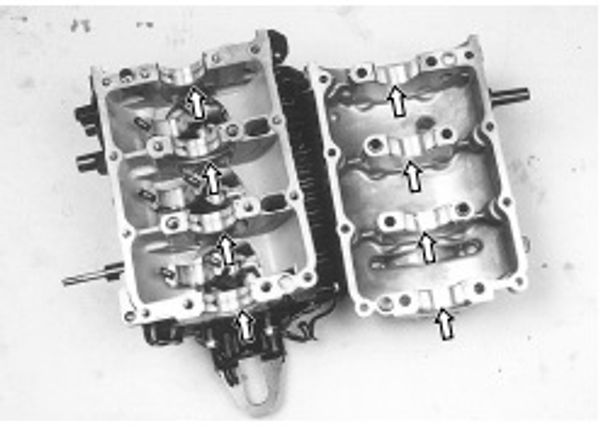
Install crankshaft main bearings in cylinder and crankcase.
Apply engine oil to bearings.
• Assemble each bearing to its original position.
• Assemble main bearing half containing oil groove / hole to cylinder block.
Assemble the half without oil groove to crankcase.
• Do not apply oil between crank bearing holder and crank main bearing.
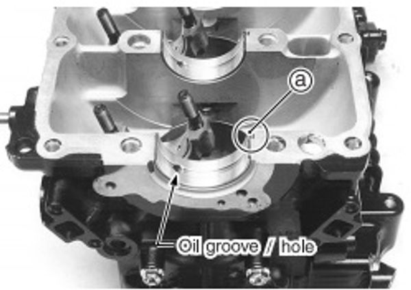
Align bearing tab a with notch in cylinder and crankcase.
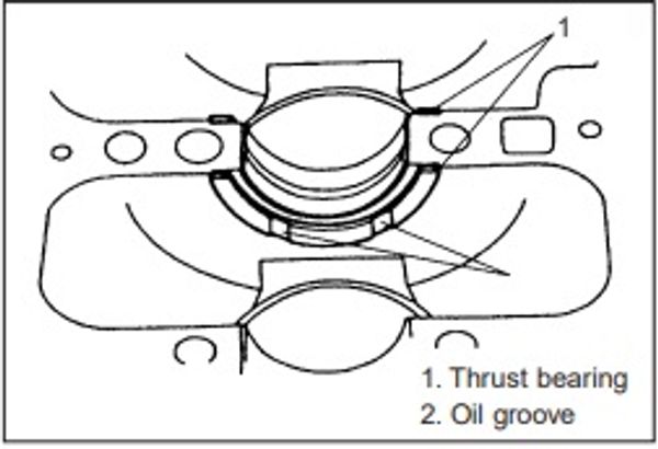
Thrust bearing
Apply engine oil to thrust bearing and install in cylinder block between the No.2 and No.3 cylinders.
Oil groove sides of thrust bearing must face towards crank webs.
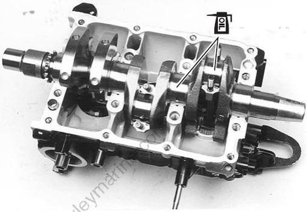
Crankshaft
Apply engine oil to crank pin and crankshaft main journal and install crankshaft in cylinder.
CONROD CAP
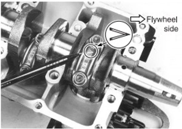
Apply engine oil to crank pin and conrod bearing.
Install conrod cap (with bearing) to conrod with arrow mark on cap toward flywheel side.
Reassemble each conrod cap to its original position.
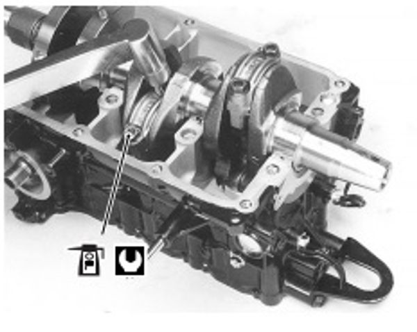
Apply engine oil to conrod bolts.
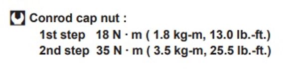
Tighten conrod cap nuts in two steps
CRANKCASE TO CYLINDER
Clean mating surface of cylinder and crankcase.
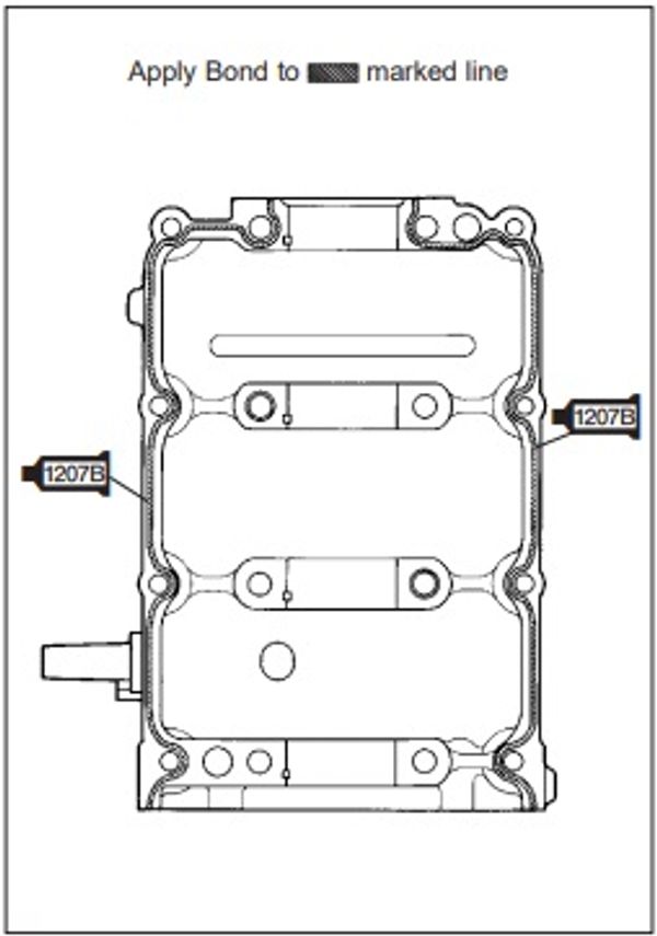
Apply SUZUKI BOND to mating surface of crankcase as shown
Apply bond to mating surface only.
Do not allow bond to contact surface of bearing.

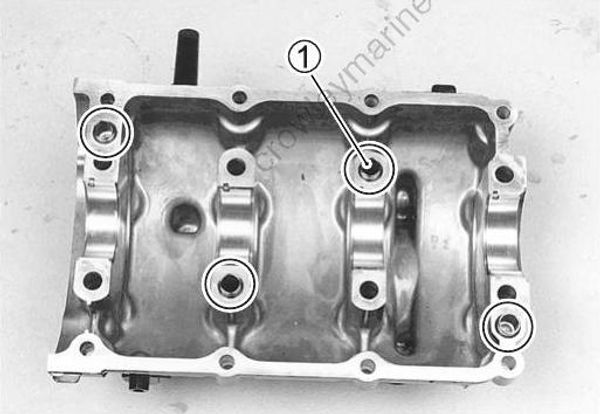
Install four (4) dowel pins (1).
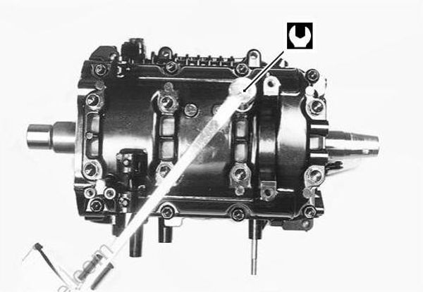
Install crankcase to cylinder.
Apply engine oil to crankcase bolts.
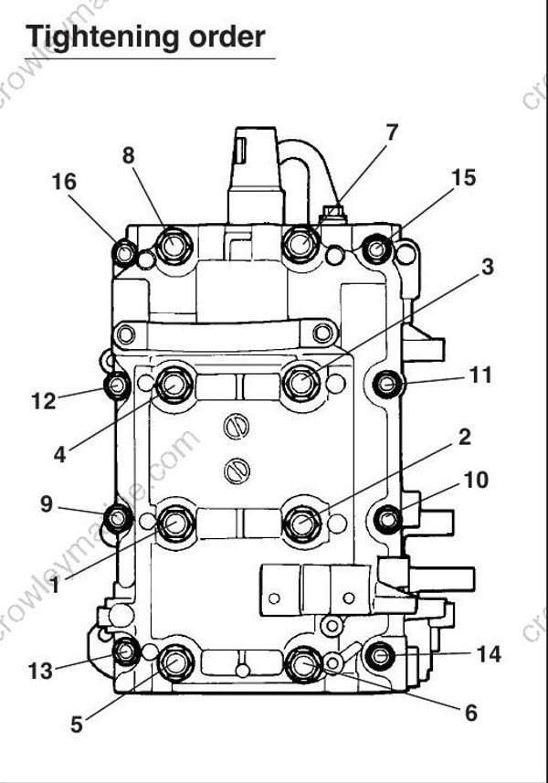
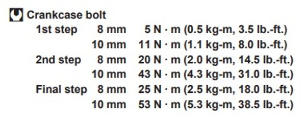
Tighten crankcase bolts in three (3) steps following the order indicated below.
After tightening crankcase bolts, check to be sure that crankshaft rotates smoothly when turned by hand.
UPPER OIL SEAL HOUSING
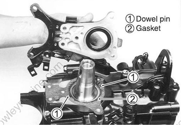
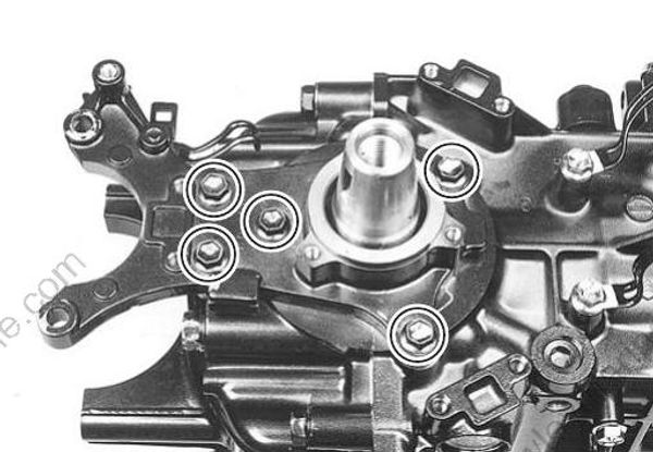
Apply engine oil to lip area of upper oil seal.
Install upper oil seal housing and secure with bolts.
