

ASSEMBLY
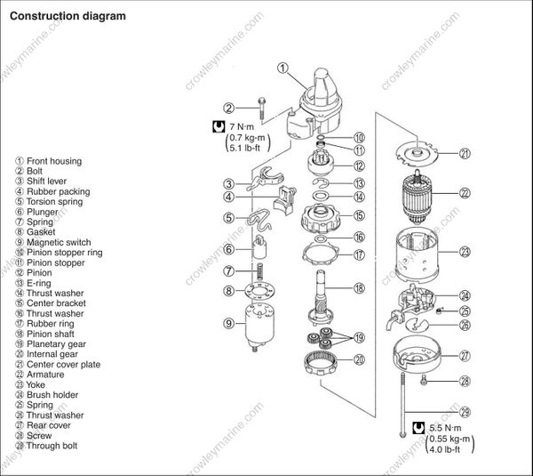
Assembly is reverse order of disassembly with special attention to the following steps.
To install the center bracket in the front housing, align the thread holes of front housing to holes of center bracket.
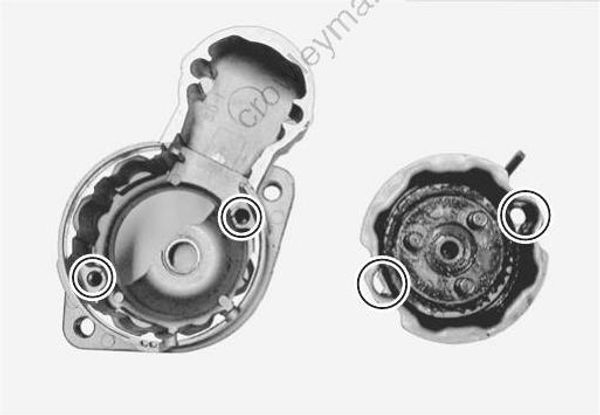
Install the internal gear as shown in figure.
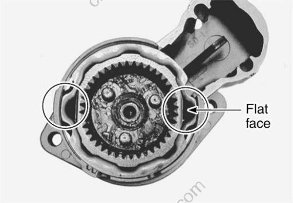
Install the center cover plate as shown in figure.
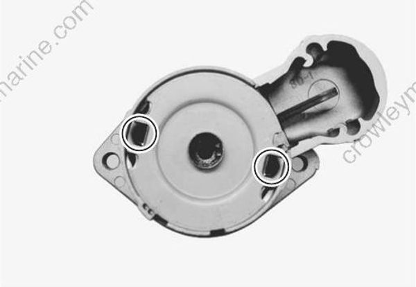
Install the brush holder as shown in figure.
When installing armature, use care to avoid breaking brushes.
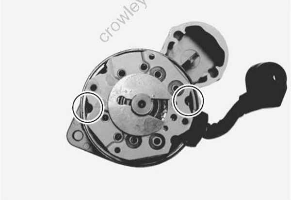
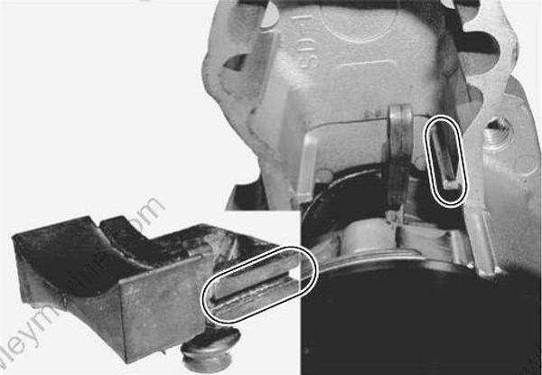
When installing the rubber packing, be sure the front housing boss properly fits into the rubber packing groove.
PERFORMANCE TEST
Each test must be performed within 3 – 5 seconds to avoid coil damage from overheating.
When performing the following test, be sure to connect the battery and the starting motor with a lead wire of the same size as original equipment used there.
PULL-IN/HOLD-IN TEST
Connect battery to magnetic switch as shown in figure.
- Check that plunger and pinion (over-running clutch) move out ward.
If plunger and pinion don’t move, replace magnetic switch.
Before testing, disconnect brush lead from terminal “M”.
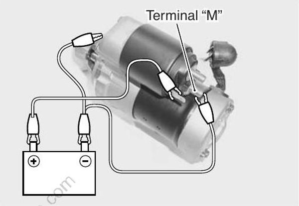
- While connected as above with plunger out, disconnect negative lead from terminal “M”.
Check that plunger and pinion remain out.
If plunger and pinion return inward, replace magnetic switch.
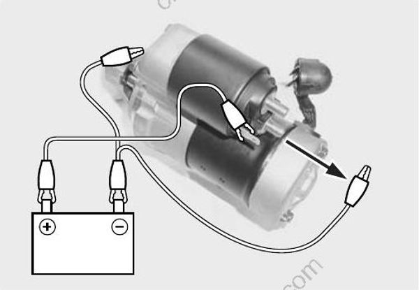
PLUNGER AND PINION RETURN TEST
Disconnect negative lead from switch/motor body. Check that plunger and pinion return inward.
If plunger and pinion don’t return inward, replace magnetic switch.
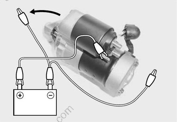
NO-LOAD PERFORMANCE TEST
Before performing following test, secure the starter motor to the test bench.
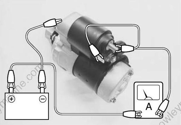
Connect battery and ammeter to starter motor as shown.
Check that starter rotates smoothly and steadily with pinion moving out. Check that ammeter indicates specified current.
No load current: Within 90 A at 11 V
REMOTE CONTROL BOX & REMOTE CONTROL WIRE
The remote control box and remote control wire have been changed.
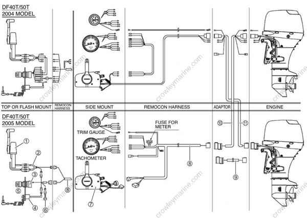
(1) Top-mount remote control box
(2) PTT switch extension wire
(3) Ignition switch
(4) Emergency stop switch
(5) Ignition & stop switch panel
(6) Caution buzzer
(7) Side-mount remote control box
(8) Remote control wire
(9) Extension wire
(10) Remote control wire adapter
(11) Remote control wire adapter
