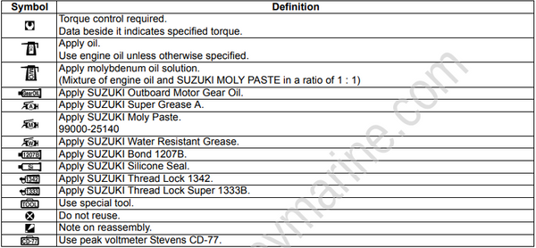
Symbols
Listed in the table below are the symbols indicating instructions and other important information necessary for proper servicing.
Please note the definition for each symbol. You will find these symbols used throughout this manual.
Refer back to this table if you are not sure of any symbol(s) meanings.
Abbreviations
Abbreviations used in this service manual are as follows:
A:
ATDC: After Top Dead Center
AC: Alternating Current
B:
BCM: Boat Control Module
BTDC: Before Top Dead Center
C:
CKP Sensor: Crankshaft Position sensor
CMP Sensor: Camshaft Position sensor
D:
DBW: Drive By Wire
DC: Direct Current
DOHC: Double Over Head Camshaft
E:
ECM: Engine Control Module
ETV: Electronic Throttle Valve
ESA: Electronic Shift Actuator
EX (Ex.): Exhaust
F:
FP: Fuel Pump
G:
GND: Ground
I:
IAT: Intake Air Temperature
IG: Ignition
Ign.: Ignition
IN (In.): Intake
L:
LPS: Lever Position Sensor
M:
MAP: Manifold Absolute Pressure
O:
OCV: Oil Control Valve
P:
PORT: Port
PTT: Power Trim and Tilt
S:
SPC System: Suzuki Precision Control System
SPS: Shift Position Sensor
STBD: Starboard
SIGP: Start-In-Gear Protection
T:
TPS: Throttle Position Sensor
V:
VSV: Vacuum Switching Valve
VVT: Variable Valve Timing
On Keyless start system model, The key operation described in this manual is as follows:
● “Turn the main switch ON position” represents that the keyless start system is turned ON by switch knob operation.
● Conversely, “Turn the main switch OFF position” represents that the keyless start system is turned OFF by switch knob operation.
Wire Color Symbols
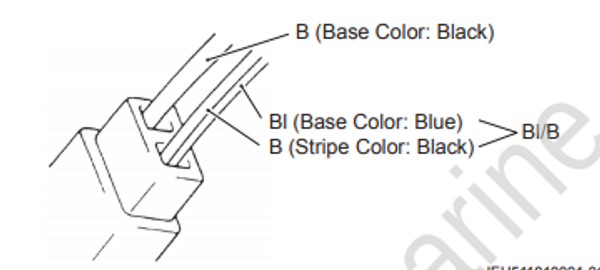
There are two kinds of colored wire used in this product.
One is single colored wire and the other is dual colored (striped) wire.
The single colored wire uses only one color symbol. example: B (Black).
The dual colored wire uses two color symbols. example: Bl/B.
The first symbol represents the base color of the wire and the second symbol represents the color of the stripe.
Example: Bl/B (Blue with Black stripe).
| Symbol | Wire color | Symbol | Wire color |
|---|---|---|---|
| B | Black | Lg | Light green |
| Bl | Blue | O | Orange |
| Br | Brown | P | Pink |
| Dg | Dark green | R | Red |
| G | Green | V | Violet |
| Gr | Gray | W | White |
| Lbl | Light blue | Y | Yellow |
IEH511010001-01
Warning, Caution and Information Label Locations
The figure shows main labels among others that are attached to outboard motor.
When servicing outboard motor, refer to WARNING/CAUTION instructions printed on labels.
If any WARNING/CAUTION label is found stained or damage, clean or replace it as necessary.
Do not reuse a label after it has been removed. Always use new label.
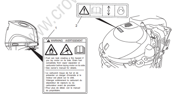
IHH511010001-01
| 1. Label, engine cover | 2. Label S.I.G.P. |
Outboard Motor Identification Number Location
Model, Pre-Fix, Serial Number
The Model, Pre-fix and Serial number of motor are stamped on a plate attached to the clamp bracket.
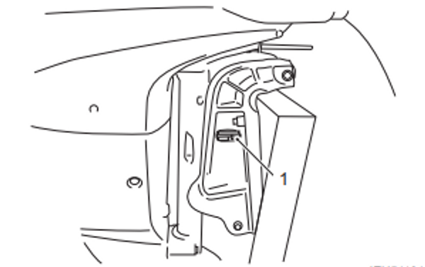
IEH511010002-03
| 1. Identification number plate |
Example
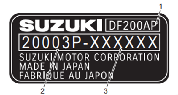
IFH513010001-02
| 1. Model | 3. Serial number |
| 2. Pre-fix |
Engine Serial Number Location
A second engine serial number plate is pressed into a boss on the cylinder block.
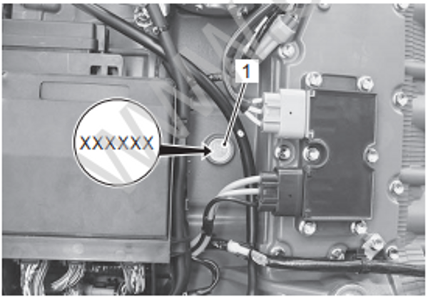
IFH513010002-01
| 1. Serial number plate |
Fuel and Oil Recommendations
Gasoline
Use of leaded gasoline can cause engine damage.
Use of improper or poor quality fuel can affect performance and may damage the motor and fuel system.
Use only unleaded gasoline. Do not use fuel having lower than the recommended octane, or fuel that may be stale or contaminated by dirt/water etc.
Allowable maximum blend of a single additive (Not combination)
5% Methanol, 10% Ethanol, 15% MTBE
Engine Oil
Use of a poor quality engine oil can adversely affect engine performance and life.
Suzuki recommends that you use Suzuki Marine 4-Cycle Engine Oil or its equivalent.
Oil quality is a major contributor to your engine’s performance and life. Always select good quality engine oil.
Suzuki recommends the use of SAE 10W-40 or 10W-30 SUZUKI MARINE 4-CYCLE ENGINE OIL.
If SUZUKI MARINE 4-CYCLE ENGINE OIL is not available, select a NMMA certified FC-W oil or good quality 4-cycle motor oil from the following chart according to the average temperatures in your area.
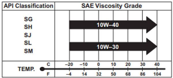
I9J011010003-02
Break-In Procedures
Failure to follow the break-in procedures described below can result in severe engine damage.
Be sure to follow the engine break-in procedures described below.
The first 10 hours are critically important to ensure correct running of either a brand new motor or a motor that has been reconditioned or rebuilt. How the motor is operated during this time will have direct bearing on its life span and long-term durability.
Break-in period
10 hours
Warm-Up Recommendation
Running at high speed without sufficient warm-up may cause severe engine damage such as piston seizure.
Always allow sufficient idling time (5 minutes) for the engine to warm-up before running at high speed.
Allow sufficient idling time (more than 5 minutes) for the engine to warm up after cold engine starting.
Throttle Recommendation
NOTE: Avoid maintaining a constant engine speed for an extended period at any time during the engine break-in period by varying the throttle position occasionally.
First 2 hours
For the first 15 minutes, operate the engine in-gear at idling speed. During the remaining 1 hour and 45 minutes, operate the engine in-gear at less than 1/2 (half) throttle (3 000 r/min).
NOTE: The throttle may be briefly opened beyond the recommended setting to plane the boat, but must be reduced to the recommended setting immediately after planning.
Next 1 hour
Operate the engine in-gear at less than 3/4 (three - quarter) throttle (4 000 r/min).
Last 7 hours
Operate the engine in-gear at a desired engine speed.
However, do not operate continuously at full throttle for more than 5 minutes.
Running continuously at full throttle for more than 5 minutes at a time during the last 7 hours of break-in operation may cause severe engine damage such as seizure.
During the last 7 hours of break-in operation, do not operate at wide open throttle for more than 5 minutes at a time.
Propeller Selection Guide
An outboard motor is designed to develop its rated power within a specified engine speed range. The maximum rated power delivered by the DF150AP/ 175AP/200AP models are shown below.
Recommended full throttle speed range
| DF150AP | 5 000 – 6 000 r/min |
| DF175AP | 5 000 – 6 000 r/min |
| DF200AP | 5 000 – 6 000 r/min |
Installing a propeller with either too much or too little pitch will cause incorrect maximum engine speed, which may result in severe damage to the motor.
Select a propeller that will allow the engine to reach the recommended operating range at full throttle with the maximum boat load.
If the standard propeller fails to meet the above requirement, use another pitch propeller to hold the engine speed within the range specified above.
Propeller size chart
| Right-hand rotation propeller Blade x Dia. (in.) x Pitch (in.) |
|---|
| 3 x 15 and 1/2 x 17 |
| 3 x 15 and 1/4 x 19 |
| 3 x 15 x 21 |
| 3 x 14 and 3/4 x 23 |
| 3 x 14 and 1/2 x 25 |
| 3 x 14 and 1/2 x 27 |
| 3 x 16 x 15 |
| 3 x 16 x 17 |
| 3 x 16 x 18 and 1/2 |
| 3 x 16 x 20 |
| 3 x 16 x 21 and 1/2 |
| 3 x 16 x 23 |
| 3 x 16 x 24 and 1/2 |
| 3 x 16 x 26 |
| 3 x 16 x 27 and 1/2 |
| Left-hand rotation propeller Blade x Dia. (in.) x Pitch (in.) |
|---|
| 3 x 15 and 1/2 x 17 |
| 3 x 15 and 1/4 x 19 |
| 3 x 15 x 21 |
| 3 x 14 and 3/4 x 23 |
| 3 x 14 and 1/2 x 25 |
| 3 x 14 and 1/2 x 27 |
| 3 x 16 x 17 |
| 3 x 16 x 18 and 1/2 |
| 3 x 16 x 20 |
| 3 x 16 x 21 and 1/2 |
| 3 x 16 x 23 |
| 3 x 16 x 24 and 1/2 |
| 3 x 16 x 26 |
Battery Requirement
Suzuki recommends a 12 V cranking type lead acid battery for the DF150AP/175AP/200AP.
Minimum battery requirement for starting the engine is provided below.
The battery must satisfy one of the specifications described below.
NOTE: ● The specifications listed below are the minimum battery rating requirements for starting the engine.
● If your boat application requires additional battery loads, it is recommended that an auxiliary battery or batteries be installed.
● Dual-purpose (Cranking/Deep Cycle) batteries can be used if they meet the minimum specifications listed below (MCA, CCA, or RC).
● Do not use a Deep Cycle battery for the main cranking battery.
● The use of Maintenance-Free, sealed, or Gel-Cell batteries is not recommended because they may not be compatible with Suzuki’s charging system.
● When connecting batteries in parallel, they must be of the same type, capacity, manufacturer, and of similar age. When replacement is necessary, they should be replaced as a set.
● It is recommended that the battery be installed in an enclosed case.
Battery specification
850 Marine Cranking Amps (MCA)/ABYC, or 670 Cold Cranking Amps (CCA)/SAE or 180 Reserve Capacity (RC) Minutes/SAE or 12 V 100 AH
- When connecting batteries, hexagon nuts must be used to secure battery leads to battery terminals.
Powerhead Direction of Rotation Description
This outboard motor is designed with a L.H. (left hand) rotation powerhead utilizing an offset crankshaft. This design has the advantage of reducing the size of the motor and keeping the overall motor’s weight closer to the boat transom and therefore closer to the boat C/G (Center of Gravity).
Rotation of the driveshaft is accomplished through a crankshaft drive gear and a driveshaft driven gear.
These gears are located beneath the powerhead in the same oil bath location as the camshaft chain.
As the rotational direction of the driven gear will be opposite of the drive gear, a left hand rotation powerhead design was adopted to retain a conventional, standard rotation (right hand) propeller shaft output.