Visual Inspections
Inspect wiring and electrical connections. Disassemble and clean all corroded connections. Replace damaged wiring, connectors, or terminals. Repair any shorted electrical circuits.
Refer to ELECTRICAL HARNESS CONNECTIONS on p. 96.
Refer to WIRING DIAGRAM at the back of this manual.
Refer to CONNECTOR SERVICING on p. 120.
Make sure all ground connections are clean and tight. Refer to GROUND CIRCUITS on p. 98.
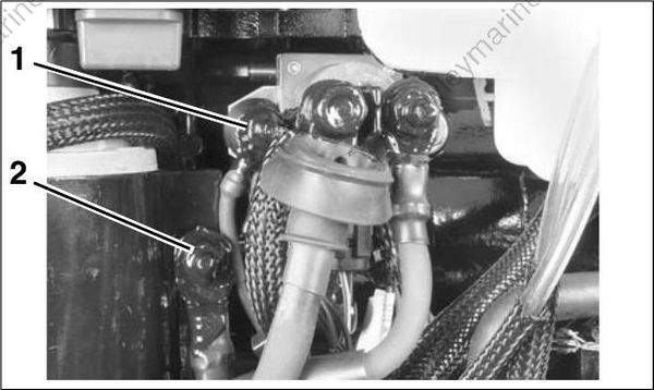
- Main engine harness ground
- Ground stud (battery)
Inspect spark plugs for wear, oil fowling, or damage. A rich or lean running condition or evidence of internal engine damage could be identified by the appearance of the spark plugs.
Check the fuse and the emergency stop switch lanyard.
Operational Inspections
Run the outboard to confirm actual symptoms before performing any unnecessary procedures. Inspection should include the following:
Make sure the outboard can be cranked easily, with no mechanical binding.
Check the EMM LED Indicators for system status information. Refer to EMM LED INDICATORS on p. 81.
Check the Evinrude Diagnostics software Active Faults and Occurred Faults screens for current service codes. Correct any problems and clear the codes before further troubleshooting. Refer to Occurred Service Codes (Faults) on p. 69.
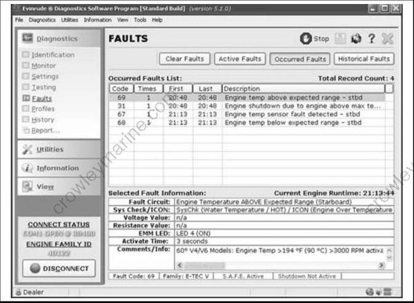
Occurred Faults Review Screen
Check the diagnostics software Profiles, Occurred, and Historical Faults screens for evidence of abnormal operation.
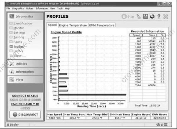
Profiles Screen
Troubleshooting
Outboard will not crank, starter does not operate:
Check condition of battery and cables (main battery switch and cables). Make sure battery cables are not reversed.
Confirm that switched B+ is present at “A” terminal (yellow/red wire) of starter solenoid with key switch in the START position.
Check ground at “B” terminal harness connection.
Refer to ELECTRIC START TESTS on p. 106. Repair starter or start circuit as needed.
Outboard cranks, will not start:
Check emergency stop switch and lanyard
Check powerhead mounted neutral switch
Check the EMM LED Indicators for system status information. Refer to EMM LED INDICATORS on p. 81.
Use the Evinrude Diagnostics software Occurred Faults screen to check for current service codes. If there are multiple occurred sensor codes, inspect all 5 V sensor circuits for broken or grounded wiring.
Perform a Static Ignition test using Evinrude Diagnostics software and an inductive timing light. Refer to Static Ignition Test on p. 85.
If ignition test indicates steady spark, refer to FUEL DELIVERY TESTS on p. 88.
Outboard runs, low on power, misfires:
Check the EMM LED Indicators for system status information. Refer to EMM LED INDICATORS on p. 81.
Use the Evinrude Diagnostics software Monitor screen to check system (55 V) and TPS volt ages. System voltage should be steady, and TPS voltage should be between 0.2 and 4.85 V.
IMPORTANT: Use a digital multimeter to check voltage on external circuits only when necessary. All EMM output currents are DC current.
Use the diagnostics software Dynamic Tests to isolate a faulty cylinder. See DYNAMIC TESTS on p. 80.
Use an inductive timing light to check ignition and fuel injector circuits. Refer to Running Ignition Tests on p. 86 and Running Fuel System Tests on p. 89.
Use the diagnostics software Fuel Control Adjustment test to help identify a cylinder that may be too rich or too lean. Refer to Fuel Control Adjustment on p. 80.
Use an inductive amp meter to monitor injector circuit current. Compare readings of all circuits to identify possible failure.
Check fuel quality and that fuel is present at injectors.
Use the diagnostics software Logging function to record engine data as a problem is occurring.
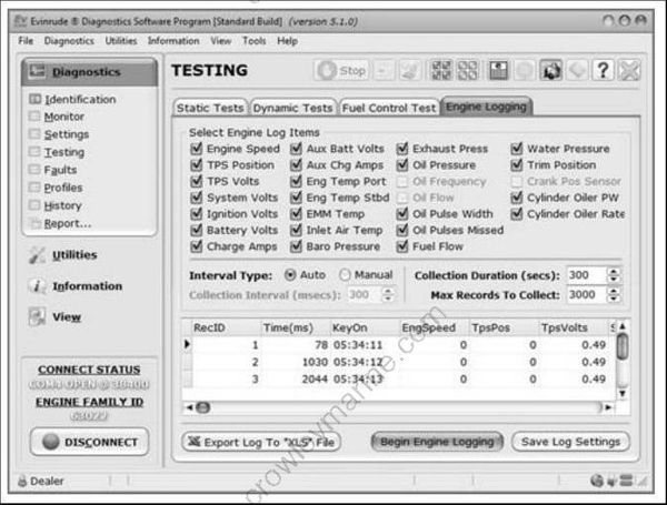
Logging Screen
- AFTER all the above inspections, if the cause of a running quality problem still cannot be identified, perform a compression test to check for internal powerhead damage.
IMPORTANT: Remove a cylinder head or disassemble the engine only as a last resort.