LIFTING THE OUTBOARD
To avoid personal injury, make sure the lifting capacity of the hoist is at least twice the weight of the outboard.
DO NOT allow the lift hook or chain from the hoist to come in contact with any part of the engine during lifting.
Use correct Lifting Fixture to lift outboard:
| Model | Lifting Fixture |
|---|---|
| 40–90 HP | P/N396748 with1 1/8 in. screws |
With recoil starter removed, Place lifting tool on flywheel and seat the three screws completely. to RECOIL STARTER REMOVAL on Refer p. 365.
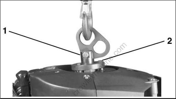
- Lifting fixture
- 1 1/8 in. screws
Use only the 1 1/8 in. (short) screws, P/N 398067, included with the tool to avoid damage to electronic components under the flywheel.
Fasten appropriate chain hook to eye of tool. Carefully hoist outboard with chain and unbolt outboard mounting brackets from frame.
OUTBOARD RIGGING CONNECTIONS
IMPORTANT: For complete outboard rigging and remote control installation information, refer the Predelivery and Installation Guide to included with the service manual set.
Common Practices – All Models
Control Cable Identification
IMPORTANT: Identify control cable function before rigging outboard.
Identify each control cable:
- Put the control handle into NEUTRAL position. The throttle cable casing guide will retract completely and the shift cable casing guide will go to the midpoint of its travel.
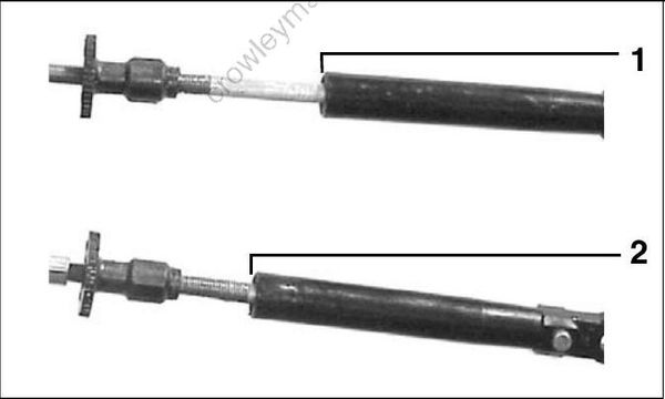
- Shift cable casing guide extended to midpoint
- Throttle cable casing guide retracted
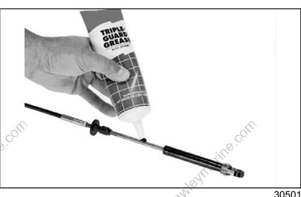
Extend the control cables and lubricate them with Triple-Guard grease.
Cable Retainer Clip Installation
When installing retainer clips on control arm link age pins, clips should be locked and must not be bent or deformed.
For proper installation, review the following steps:
Place washer on pin.
Position retainer clip with straight section on the bottom and angled section on the top.
Use long nose pliers to insert straight section of clip into linkage pin hole.
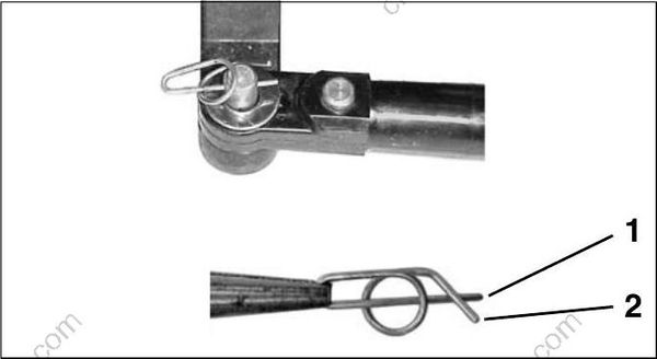
- Straight section
- Angled section
Push the clip towards the hole while lifting on the curved end with the pliers.
Be sure retainer clip fully engages the pin.
Lock the retainer by moving the angled section behind the straight section.
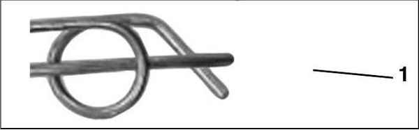
Locked Retainer Clip
- Angled section behind straight section
Cable, Hose, and Wire Routing
To prevent accidental starting while servicing, disconnect the battery cables at the battery. Twist and remove all spark plug leads.
Refer to Control Cable Identification on p. 21.
Apply soapy water to the inside surfaces of grommet and install cables and fuel line as shown:
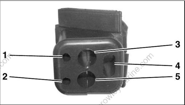
- Throttle cable
- Shift cable
- Main wiring harness
- Battery cable
Place the grommet into position in the lower engine cover.
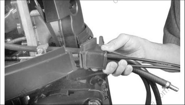
When grommet is in place and all cables have been installed, tighten a tie strap around the outside of the grommet to form a watertight seal around the cables.
After installation, make sure there is enough clearance for all cables to avoid binding or chafing through all engine steering and tilting angles.
Control Cable Installation
Refer to Control Cable Identification on p. 21.
Remove cable retainer from anchor block. Apply Triple-Guard grease to both anchor block pockets.
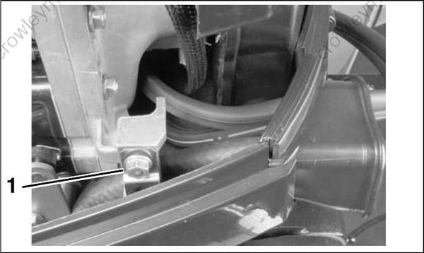
- Cable retainer
IMPORTANT: DO NOT secure cables to throttle and shift lever pins until all cables, wires, and hoses have been routed and grommet has been installed in the lower engine cover.
Make sure the remote control is in NEUTRAL, and throttle is in the IDLE position.
Pull firmly on shift cable casing to remove slack. With outboard in NEUTRAL, place the cable trunnion into the lower anchor pocket. Adjust the trunnion nut so the casing fits onto the shift lever pin.
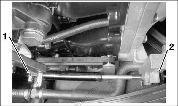
- Shift lever pin
- Trunnion nut
If there are not enough threads on the shift cable for the adjustment, or if the gearcase does not shift fully into FORWARD or REVERSE, refer to SHIFT ROD ADJUSTMENT on p. 296, or SHIFT ROD ADJUSTMENT on p. 319.
With remote control lever in NEUTRAL, pull firmly on throttle cable casing to remove slack.
With engine throttle lever against stop, place the cable trunnion into the upper anchor pocket and adjust the trunnion nut so the casing fits onto the throttle lever pin.
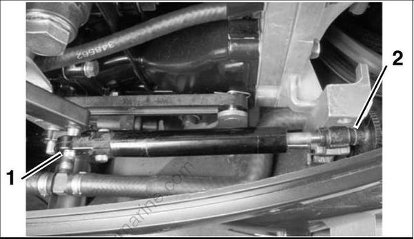
- Throttle lever pin
- Trunnion nut
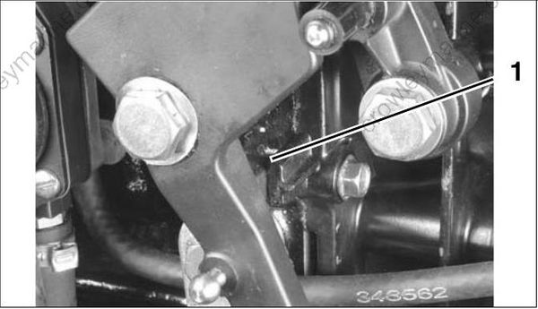
- Throttle lever stop – 3 Cylinder models
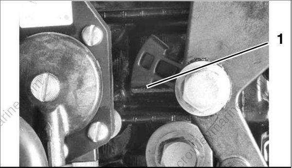
- Throttle lever stop – 2 Cylinder models
IMPORTANT: Move control handle to FOR WARD and pull back slowly to NEUTRAL. Make sure the engine throttle lever is against the stop. If not, remove slack by adjusting cable trunnion.
After grommet has been installed in lower engine cover, install the washers and retainer clips on the throttle and shift lever pins. Refer to Cable Retainer Clip Installation on p. 22.
Install cable retainer and screw. Tighten screw to a torque of 60 to 84 in. lbs. (7 to 9.5 N·m).
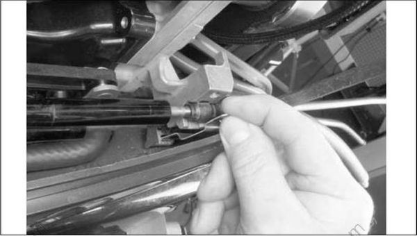
SystemCheck Harness Connections
Place the wiring harness through notch in lower motor cover and route to the recess in the fly wheel cover. Secure the cable with a tie strap as shown:
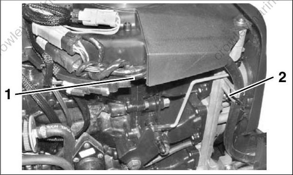
- Recess
- Tie strap
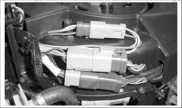
Before installing electrical connectors, check that the seal is in place. Clean off any dirt from connectors. Apply a light coat of Electrical Grease to the seal only. DO NOT fill connectors with Electrical Grease.
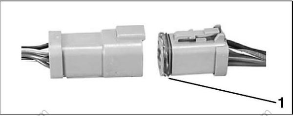
- Seal
Arrange connectors in flywheel cover.
Install electrical cover and secure with screws.
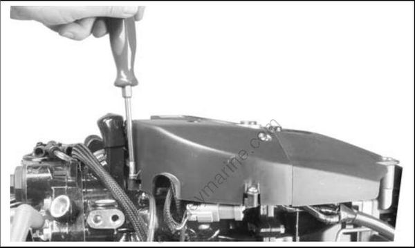
BE SURE all harnesses and wires are not pinched, cannot contact flywheel, and do not interfere with moving throttle or shift linkages.
I-Command Network Connections
If the outboard will be used with I-Command, or other NMEA 2000 compliant CANbus instruments, use the following connections to supply information to the network:
Remove lower motor covers. Remove air silencer. Route I-Command Engine Interface Cable around the front of the throttle body, following the path of the TPS wiring, and behind the battery cable. Loosely install tie straps as shown.
To prevent wire chafing, harness must be routed below the flywheel cover.
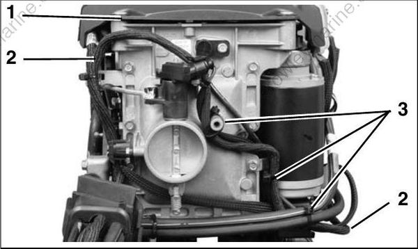
2 Cylinder Models
- Flywheel cover
- Harness routing
- Tie straps
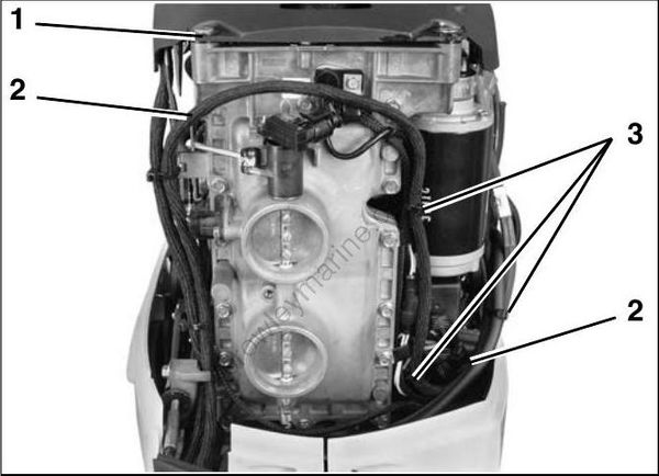
3 Cylinder Models
- Flywheel cover
- Harness routing
- Tie straps
Connect the I-Command Engine Interface Cable to the EMM CANbus connector.
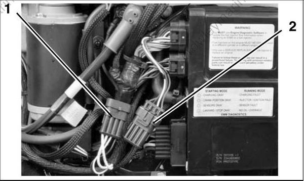
- I-Command network connector
- EMM CANbus connector
2 CYLINDER MODELS
To prevent interference with engine cover latch, bundle excess wiring behind EMM cooling water hose. Secure I-Command connectors to back side of engine harness with tie strap.

- Engine harness
- EMM cooling water hose
3 CYLINDER MODELS
EMM CANbus connector cap is clipped to EMM cooling water hose. Remove clip from cap and install on I-Command harness connector.
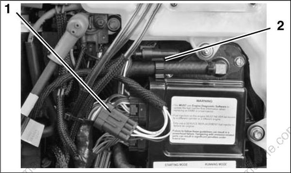
- Canbus harness connector
- EMM CANbus connector cap and clip
Install clip and connector to hose.
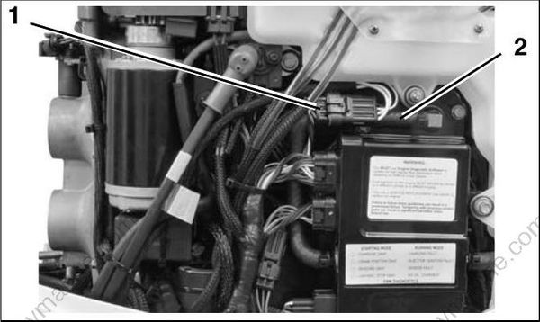
- CANbus connectors
- EMM cooling water hose
ALL MODELS
Adjust harness routing as needed and secure with tie straps.
Use an I-Command Ignition and Trim Harness to connect the outboard to the key switch and trim/tilt control. Seal unused SystemCheck connector with 6-Pin Connector Seal, P/N 586076.
If connecting to an existing I-Command Classic network, connect the purple wires between the I-Command Ignition and Trim Harness and the I-Command Engine Interface Cable. This connection supplies power to the network when the key switch is on. I-Command Digital networks do not use this connection.
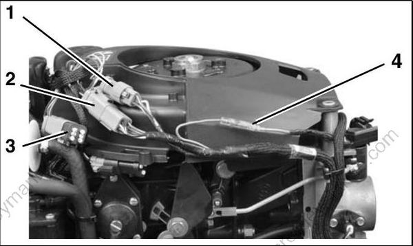
- Trim/Tilt connector
- CANbus Ignition connector
- SystemCheck connector (with seal)
- Deutsch-style harness power connector
Route I-Command Ignition Harness through wire channel in flywheel cover. Install electrical cover. Make sure both harnesses are in front of the tab and tighten with tie strap.
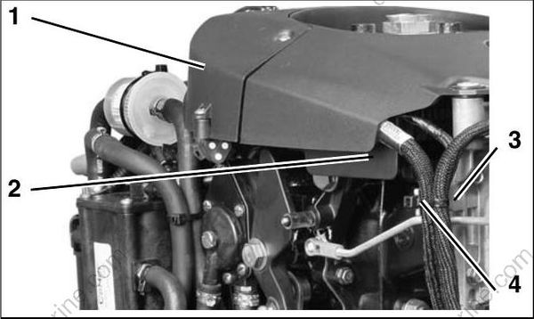
- Electrical cover
- Wire channel
- Tab
- Tie strap
Use Evinrude Diagnostics software to adjust network settings in the EMM. From the Settings screen, select Engine Options.
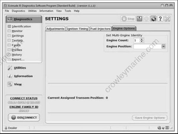
Engine Options Screen
Water Pressure Gauge
To display engine water pressure, install a water pressure hose fitting in the cylinder block as shown.
Use Pipe Sealant with Teflon on the threads of the hose fitting. Refer to installation instructions sup plied with gauge.
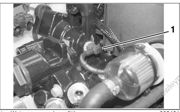
For an I-Command water pressure display, several water pressure sensor kits are available. Refer to the Evinrude/Johnson Genuine Parts and Accessories catalog.