DIAGNOSTIC SOFTWARE FUNCTIONS
The EMM stores valuable information about the outboard and its running history. This information can be used for troubleshooting, for checking parts information, and for making adjustments to the system.
Use Evinrude Diagnostics software, version 5.1 or higher, and a laptop computer to access program information.
IMPORTANT: For software help, refer to the “Help” menu in the software.
Communication
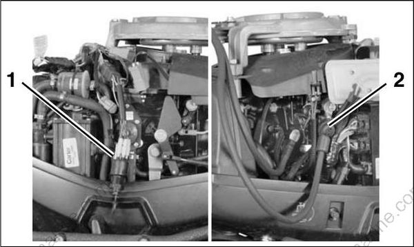
Locate the diagnostic connector on the engine. Remove the cover and install the Diagnostic Inter face Cable (P/N 437955).
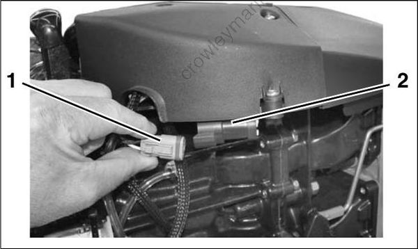
- Diagnostic connector
- Cover
Connect the 9-pin connector of the interface cable directly to the computer’s serial port.
The EMM must turn ON before it will communicate with the computer.
ELECTRIC START MODELS
Power is normally supplied to the EMM when the key switch is ON. Switched B+ (12 V) enters the EMM at pin 28 (purple) of the EMM J1-B connector.
The EMM is also turned ON when it begins to receive AC voltage from the stator while the outboard is being cranked.
ROPE START MODELS
Diagnostic communications on non-running rope start models requires a power supply to the EMM.
Use Diagnostic Power Supply Tool, P/N 587005, to supply power to the EMM. The power supply uses internal 9-volt batteries.
Disconnect the tiller handle harness connector from the engine harness. Connect Power Supply Tool to the engine harness connector. Turn toggle switch to the ON position to power the EMM.
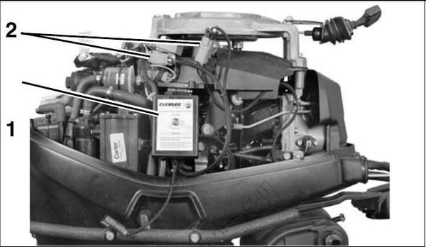
- Power supply tool
- Engine harness connectors
IMPORTANT: Static tests require more power than the internal batteries of the tool can provide. Static tests performed using only the internal power supply batteries will produce false results.
Use Accessory Power Cable Kit, P/N 5008092, to connect an external 12 volt battery to the Power Supply Tool when performing these static tests:
- Fuel pump
- Fuel injector
- Ignition coil
- Oil injector
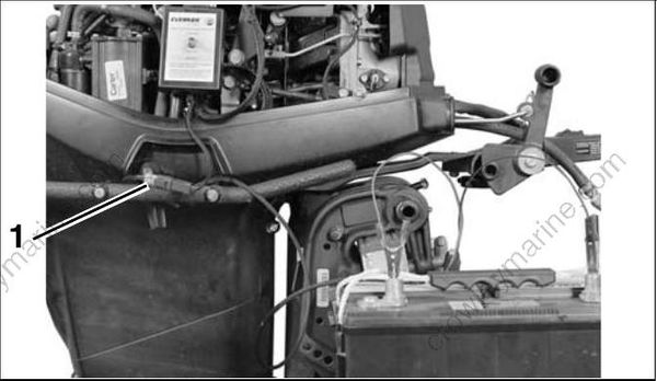
- External power connector
If Diagnostic Power Supply Tool, P/N 587005, is not available, a Battery Cable, P/N 584348, can be connected to the engine mounted solenoid. Use accessory Key Switch Assembly, P/N 176408, to control power to the EMM.
- Accessory key switch
- Battery cable
Static Information
Static information is viewed when the outboard is NOT running. This includes manufacturing information.
The outboard model and serial numbers displayed on the Identity screen must match the identification label on the outboard swivel bracket.
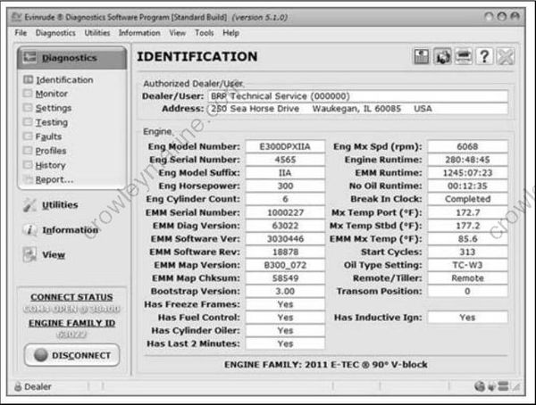
Identity Screen
The serial number and cylinder location displayed on the Injector Coefficients screen must match the actual cylinder placement for each injector.
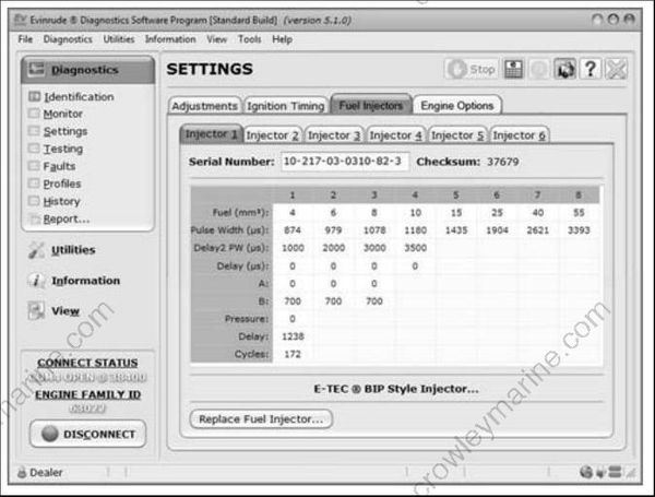
Injector Coefficients Screen
Dynamic Information
Dynamic information is viewed while the outboard is running. Changes in data, such as voltages or temperatures, are shown as they happen.
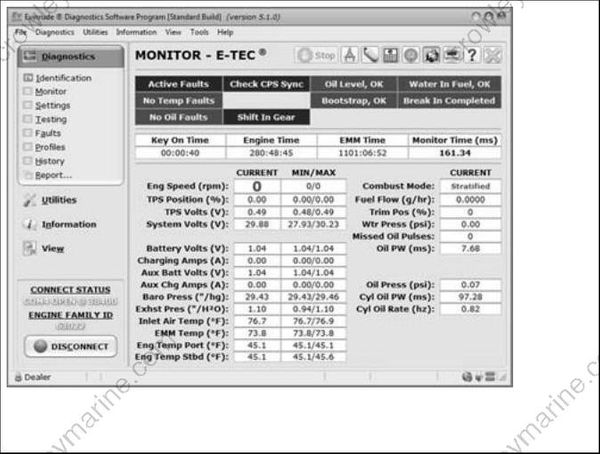
Monitor Screen
Occurred Service Codes (Faults)
Service codes are saved if an abnormal condition occurs while the outboard is running.
The Occurred Faults screen of the diagnostics software shows the code number, the number of times the event occurred, and operating hours of first and last occurrences.
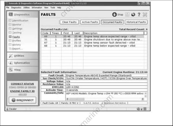
Occurred Faults Review Screen
Active Faults
An active fault is a service code that currently exists. Active faults become occurred faults only if the outboard is running.
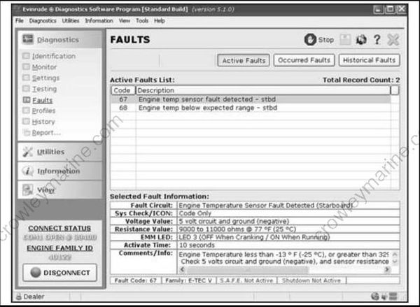
Active Faults Review Screen
Historical Faults
The Historical Faults screen keeps a history of all previously saved codes, including code number, the number of times the event occurred, and operating hours of the last occurrence.
Historical faults cannot be erased.
Static Tests
Static Tests allow diagnostic testing of system components while the outboard is NOT running.
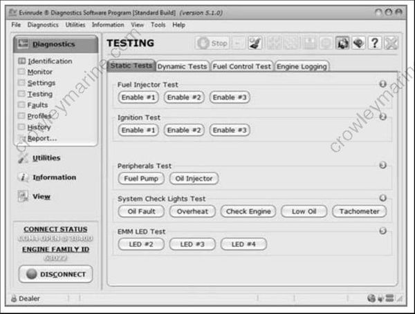
Static Tests Screen
Ignition Test
Use the diagnostics software to test each ignition circuit. Refer to Static Ignition Test on p. 85.
Fuel Test
Use the diagnostics software to test each fuel injector circuit. Refer to Fuel Injector Static Test on p. 88.
Oil Injector
Use the diagnostics software to test the oil injection pump circuit. Refer to OILING SYSTEM TESTS on p. 170.
Fuel Pump
Use the diagnostics software to test the fuel pump circuit. Refer to Fuel Pump Static Test on p. 88.
Water Injector
This test activates the exhaust water valve solenoid (60 - 65 HP). Refer to Exhaust Water Valve Static Test on p. 90.
Overheat
This test is used to check the “ENG TEMP” or “HOT” circuit of the Engine Monitoring system.
Oil Fault
This test is used to check the “NO OIL” circuit of the Engine Monitoring system.
Check Engine
This test is used to check the “CHECK ENGINE” circuit of the Engine Monitoring system.
Tachometer
This test is used to check operation of the tachometer circuit.
Dynamic Tests
Dynamic tests are performed with the outboard running.
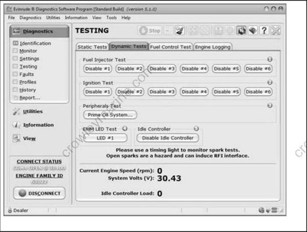
Dynamic Tests Screen
Ignition Test
This test momentarily disables the ignition and fuel injection circuits to one cylinder. By dropping one cylinder, RPM and running quality changes can be observed. Refer to DYNAMIC TESTS on p. 80
Fuel Test
This test momentarily disables one fuel injector circuit. By dropping one cylinder, RPM and running quality changes can be observed. Refer to DYNAMIC TESTS on p. 80.
Prime Oil
This test is used to cycle the oil injection pump for priming the oiling system. Perform this test with outboard running to activate oil injection pump.
Oil Control Settings
Set Oil Type
The TC-W3 oil type setting is the standard setting for all outboards. Set TC-W3 for:
• Operation with all TC-W3 outboard oils including XD30, XD50, or XD100
• Applications requiring maximum lubrication
• Extreme applications (racing or harsh conditions).
The XD100 setting provides an option to run the outboard at a reduced oil injection rate. This setting REQUIRES the use of Evinrude XD100 outboard lubricant and is not recommended for all applications.
Use the XD100 setting for:
• Conventional use (runabouts, cruisers)
• Moderate applications.
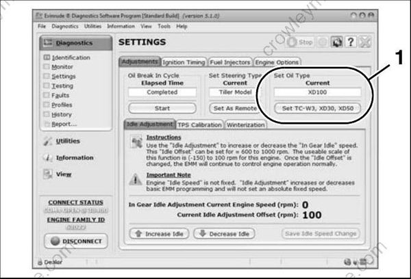
- Oil control setting
Running an Evinrude E-TEC outboard on other grades of oil while set to the XD100 oil ratio will result in increased engine wear and shortened outboard life.
Powerhead Break-In
Use the diagnostics software to start break-in oiling after a powerhead rebuild. The break-in oiling program runs for two hours of outboard operation, above 2000 RPM.
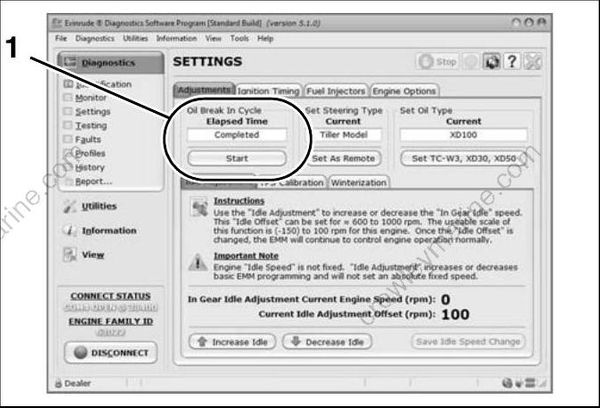
- Break-in oil setting
Tiller/Remote Programming
This feature controls the start in gear protection function of the neutral switch. Tiller operated models, including remote models with an installed tiller conversion kit, MUST be set to TILLER.
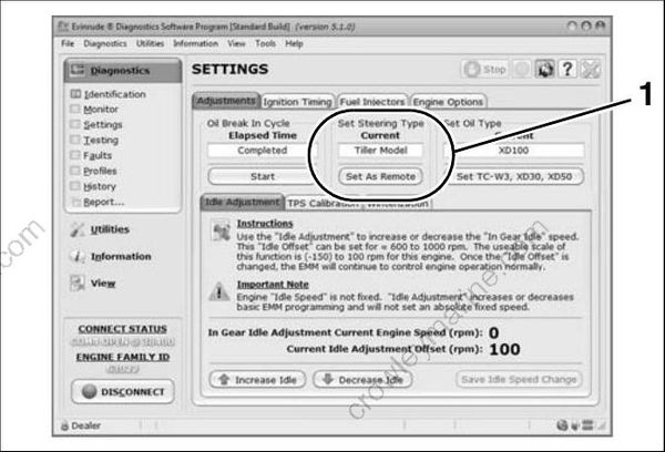
- Starter mode setting
Ignition Timing
Use the Ignition Timing screen to check and adjust EMM timing. EMM timing must be synchronized to crankshaft position.
Refer to TIMING ADJUSTMENTS on p. 117
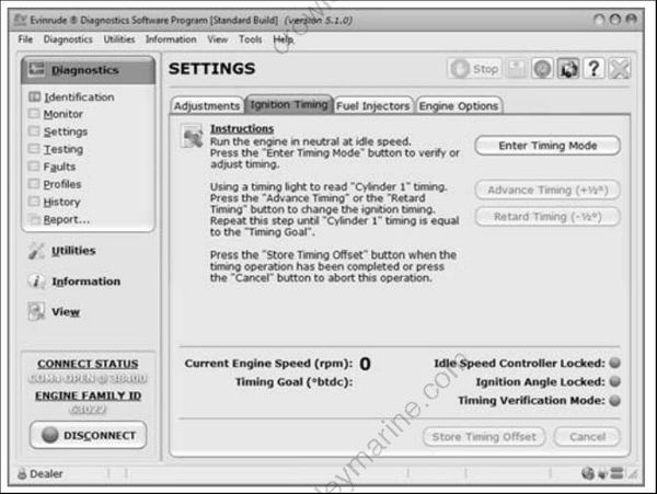
Check timing after any of the following procedures:
- Powerhead replacement
- Crankshaft replacement
- Flywheel removal or replacement
- CPS replacement
- EMM replacement
- EMM software replacement
IMPORTANT: Make sure the timing pointer is set and the outboard reaches operating temperature before making adjustments.
TPS Calibration
TPS Calibration synchronizes throttle plate opening with throttle position sensor voltage.
Refer to TPS Calibration on p. 118.
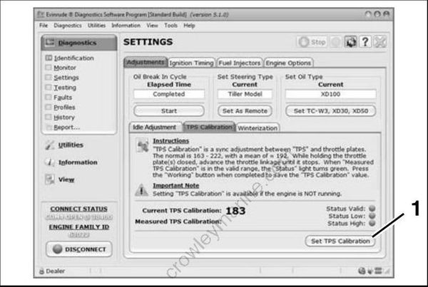
- TPS Calibration button
Perform TPS Calibration after replacing or adjusting any throttle body or throttle linkage parts.
Idle Speed Control
Use the Idle Adjust function to increase or decrease IN GEAR IDLE speed. This adjustment offsets the basic EMM programming and will not set an absolute fixed speed. After the offset is changed, the EMM continues to control engine operation normally. Engine idle speed is not fixed.
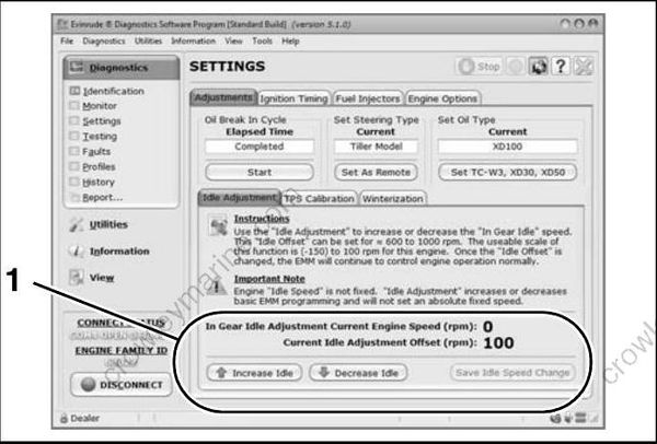
- Idle adjustment
Fuel Injector Servicing
All E-TEC fuel injectors use software programming to compensate for variations in fuel flow. Each injector and its location on the outboard is identified by the EMM. DO NOT install an injector without updating the compensation software.
To install a service injector, click the “Replace” button on the Injector Coefficients screen and select the file for the replacement injector. Refer to Fuel Injector Service on p. 150.
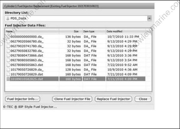
Reports
Engine reports provide service records and can be used to document the running history of an outboard. Reviewing this information can help identify or resolve some service issues.
Click the print button in a window of the diagnostics software to print engine data, or to export the information to a computer file.
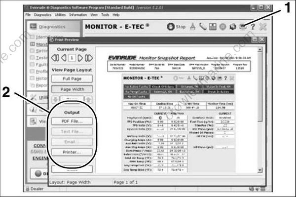
- Print button
- Print/Export options
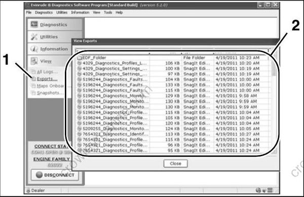
Engine Report data files
- Exports button
- Data files
Software Replacement
Engine Management Software is loaded into the EMM at the factory. Periodically, a new program may be available to enhance the operation of an outboard. Select Engine Software Update from the Utilities menu and refer to the instructions provided with the program.
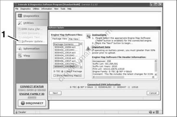
- Software Update button
IMPORTANT: If using Diagnostic Power Supply Tool, P/N 587005, to supply power to the EMM, use Accessory Power Cable Kit, P/N 5008092, to connect an external 12 volt battery to the Power Supply Tool.
If the internal batteries of the Power Supply Tool have a low voltage condition the EMM could turn OFF during the software upload, resulting in a failed software update.
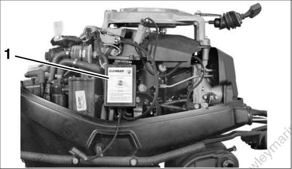
- Power supply tool