

COMPONENTS
The oiling system includes the following components:
Oil tank
Oil injection pump and manifold assembly
Oil level switch
Electrical circuit
LOW OIL and NO OIL warning systems
Cylinder and crankcase
Oil recirculation system.
Oil Tank Assembly
The oil tank is mounted on the powerhead under the engine cover. Oil level must be monitored.
Oil Tank Components:
Tank, 2 quart. (1.87 liter) capacity
Oil pickup and filter assembly
Oil injection pump and manifold assembly
LOW OIL switch
Oil distribution hoses
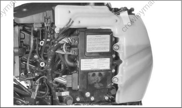
Oil Injection Pump
The oil injection pump is an electric (55 V) actuator style pump. It draws oil from the oil tank and supplies pressurized oil to the oil manifold. The EMM supplies 55 V and controls activation of the pump.
The oil manifold distributes the oil supplied by the pump.
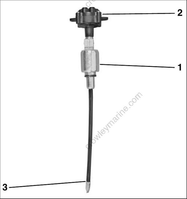
- Oil injector pump
- Oil distribution manifold
- Pickup tube and filter
Electrical Circuit (55 V)
The oil injector is powered by the 55 V electrical circuit. The EMM controls pump operation by rapidly connecting and disconnecting the pump’s internal coil to ground.
The EMM monitors the oil injection pump electrical circuit. If circuit voltage is beyond the specified range, or the circuit is open, the EMM:
Activates S.A.F.E.
Stores a service code 34
EMM LED 4: ON (Running)
Gauge (opt) NO OIL display: ON
LOW OIL Warning
IMPORTANT: The SystemCheck engine monitor warning system is available for MFE 55 models through the installation of boat Harness Kit P/N 586853.
A switch in the oil tank pick-up assembly monitors the oil level in the oil tank.
If the oil level falls below one-quarter capacity, the EMM:
Interrupts the ignition once per 50 engine revolutions to signal the operator
Gauge (opt) LOW OIL display: ON
Approximate oil reserve at Low Oil activation:
- 0.45 qt. (0.43 l).
NO OIL Warning
When the oil level falls below one-quarter, the EMM begin s coun ting oil pump pulse cycle s. When it reaches 4800 pulses, the EMM:
Activates S.A.F.E.
Stores service code 117
EMM LED 4: ON (Running)
Gauge (opt) NO OIL display: ON
To recover from S.A.F.E. mode:
Oil level must be above one-quarter
The warning re sets after three oil pump pulse cycles when the out board has been stopped and restarted.
If outboard has been run for more than 3 hours with NO OIL faults (codes 34 & 117), the EMM
Stores service code 33
EMM LED 4: FLASHING
Gauge (opt) NO OIL display: FLASHING
Cylinder and Crankcase
The oil distribution manifold provides crankcase lubrication thro ugh oil distribution hoses and pressed-in fittings on the crankcase and cylinder block.
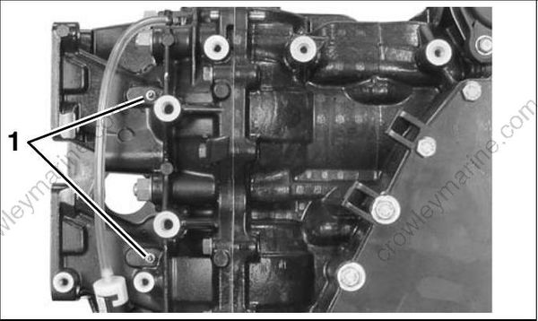
- Crankcase oil fittings
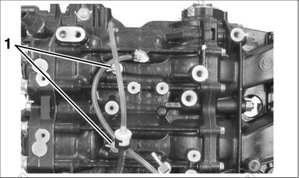
- Cylinder block oil fittings
Oil Recirculation System
External hoses an d fittings, internal cylinder/crankcase passages, and intake manifold passages are used to recirculate any accumulation of oil from various locations in the powerhead. The movement of oil is controlled by check valves.
Cylinder Recirculation
Internal powerhead oil drain passages connect the intake port areas of the cylinders to circulate residual oil in the block.
External fittings and in-line check valves on each side of the cylinder block control the movement of oil from the lower cylinder port to the upper cylinder port.
Crankcase / Main Bearing Recirculation
The movement of oil through the main bearings is controlled b y internal passages, external fitting s and hoses, and check valves.
Lower to upper main bearing oil flow:
Lower main bearing cavity to internal crankcase passage to external fitting, external hoses with in-line check valve to external fitting at up per main bearing, and into upper main bearing through internal crankcase passage.
Internal crankcase passage to external fitting in crankcase cover at upper main bearing, hose routed to reed plate fitting. This circuit vents the upper main bearing cavity to promote oil flow.
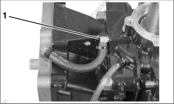
- Upper main bearing vent
Refer to the OIL RECIRCULATION DIAGRAM on p. 158.
OIL CONTROL SETTINGS
Oil Injection Rate
EMM programming controls the rate of oil injection based on engine RPM. This rate can be adjusted for powerhead break-in. Use Evinrude Diagnostics software to access this feature.
Break-In Oiling
The EMM automatically supplies extra oil to the
engine during the first two hours o f operation,
above 2000 RPM.
Follow these steps for outboard set-up:
Use Evinrude Diagnostics software to make sure the break-in program has been started on
a new outboard.Use the diagnostics software to start break-in oiling after a powerhead rebuild.
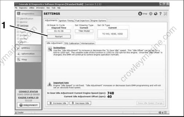
- Break-in oil setting
The operator must monitor the oil tank level to confirm oil consumption. This may require several hours of operation above idle.
Oil Priming
The oiling system of the outboard must be primed:
When the outboard is first installed.
Whenever the oil supply to the oil lift pump is disconnected or disrupted.
Whenever an oiling system component is removed or replaced.
Refer to Oil Supply Priming on p. 39.
