

EXTENSION SERVICE – V4 Models
Removal
Remove six screws retaining extension.
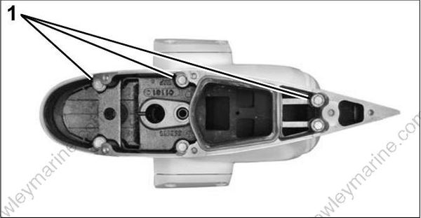
- Screws
Remove extension.
Remove grommets and seal.
Installation
Apply Adhesive 847 to the shift rod and water tube flange of the extension. Install new grommets.
Apply Triple-Guard grease to outer grommet surfaces.
Apply Adhesive 847 to the bottom flange of the extension. Install a new seal.
Apply Triple-Guard grease to outer seal surface.
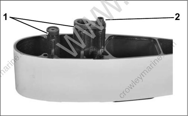
- Adhesive 847
- Triple-Guard grease
Install extension with six screws and tighten to a torque of 18 to 20 ft lb. (24 to 27 N•m).
STERN BRACKET
Stern Bracket Disassembly
Before servicing the stern bracket:
- Remove gearcase. Refer to Gearcase GEARCASE REMOVAL AND INSTALLATION on p. 268.
- Remove powerhead. Refer to Powerhead POWERHEAD REMOVAL on p. 196.
- Remove exhaust housing. Refer to Exhaust Housing Exhaust Housing Removal on p. 242.
- Remove power trim/tilt unit. Refer to TRIM AND TILT section.
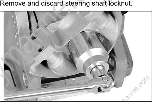
Remove and discard steering shaft locknut.
Remove the lower mount bracket and keeper.
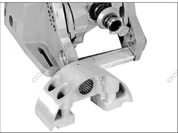
Remove the steering shaft and thrust washer. It may be necessary to tap the steering shaft out using a wood dowel and mallet.
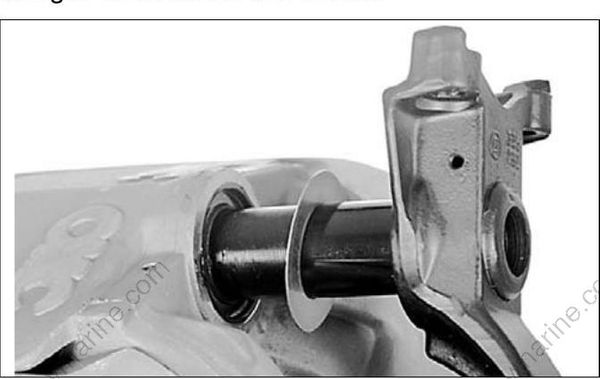
Pry out upper and lower steering shaft seals and discard. Remove the upper and lower steering shaft bushings.
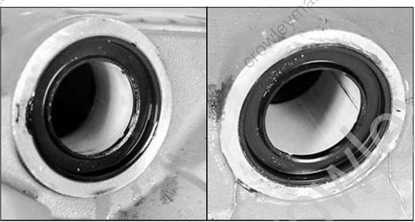
Remove the tilt tube. Refer to TILT TUBE on p. 240.
Remove the two tilt tube washers.
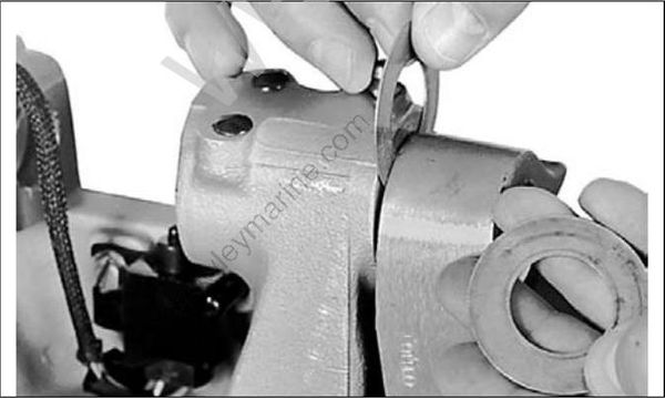
Remove the anode.
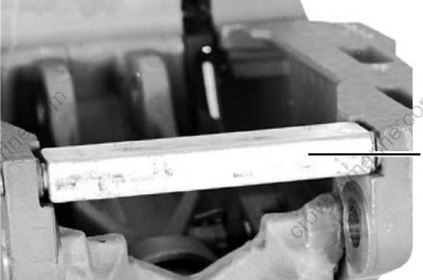
- Anode
Remove the swivel bracket. Inspect and, if necessary, replace the tilt tube bushings.
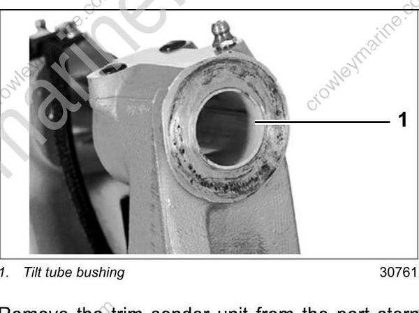
- Tilt tube bushing
Remove the trim sender unit from the port stern bracket and pull its wires through the braided tube.
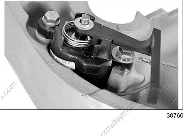
Remove the tilt limit switch and retainer from the swivel bracket.
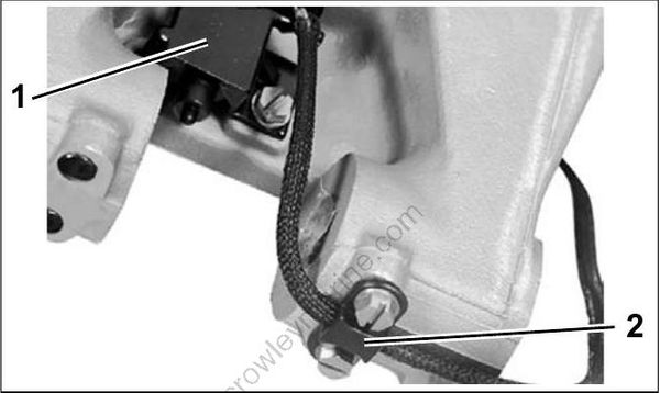
- Tilt limit switch
- Retainer
Disconnect the trail lock spring and remove it from the swivel bracket. Remove trail arm retainer.
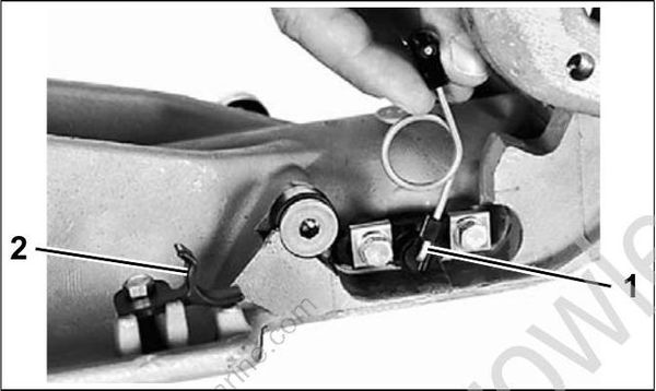
- Trail lock spring
- Trail arm retainer
Remove the trail lock arm and bushings from the swivel bracket.
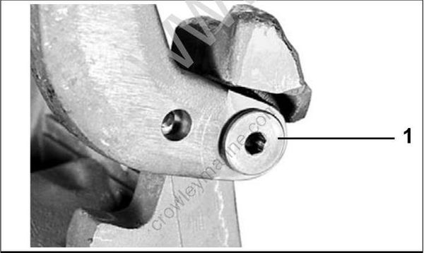
- Trail lock bushing
Remove the two trim rod rollers from the swivel bracket.
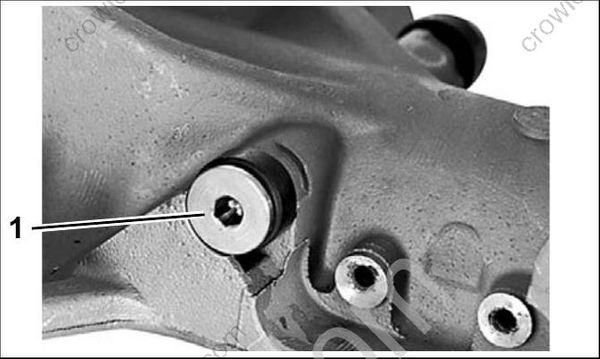
- Trim rod roller
Remove the tilt support and bushing from the swivel bracket and inspect the detent roller and spring.
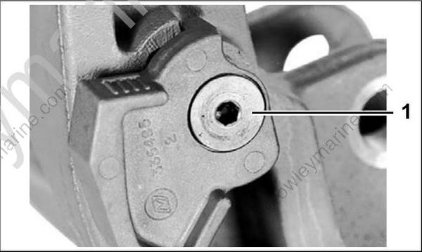
- Tilt support bushing
Stern Bracket Assembly
IMPORTANT: Before proceeding, make sure all components have been thoroughly cleaned. Replace any seals that have been removed. Inspect all thrust washers and bushings for evidence of deterioration.
Install the detent roller and spring and the tilt support with bushing in the swivel bracket. Tighten bushing to a torque of 28 to 30 ft. lbs. (38 to 41 N•m).
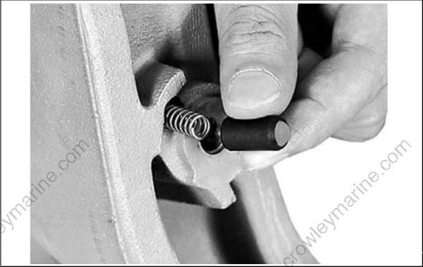
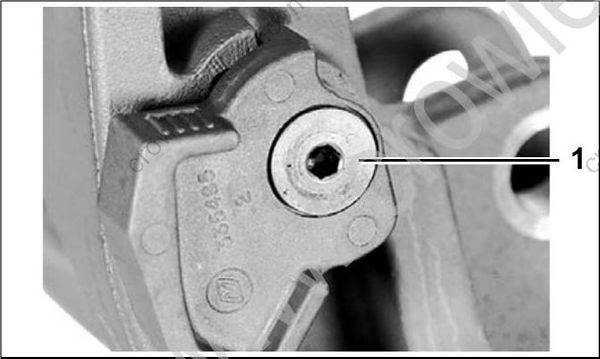
- Tilt support bushing
Install the two trim rod rollers on the swivel bracket. Tighten to a torque of 216 to 240 in. lbs. (25 to 27 N·m).
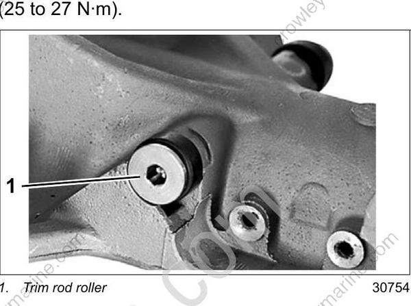
- Trim rod roller
Install the trail lock and bushings in the swivel bracket. Tighten to a torque of 216 to 240 in. lbs. (25 to 27 N·m).
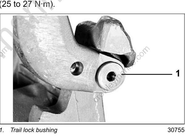
- Trail lock bushing
Install the trail lock and spring in the swivel bracket and connect the spring to the trail lock.
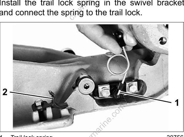
- Trail lock spring
- Trail arm retainer
Install the tilt limit switch and retainer on the swivel bracket. Tighten screws to a torque of 40 to 50 in. lbs. (4.5 to 5.5 N•m).
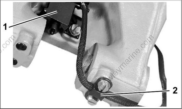
- Tilt limit switch
- Retainer
Route the trim sender wires through the braided tube, and install the sender unit in the port stern bracket.
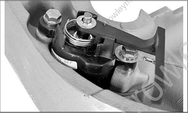
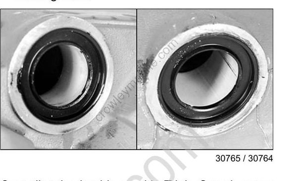
Install the upper and lower steering shaft bushings and new seals in the swivel bracket. Both seal lips face out.
- Coat the outside surfaces of seals with Gasket Sealing Compound.
- Coat the bushings and seal lips with Triple Guard grease.
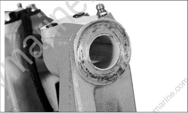
Coat tilt tube bushings with Triple-Guard grease and, if removed, install them in the swivel bracket.
Place the swivel bracket between the stern brackets and install the anode.
Install the tilt tube and tilt limit cam. Refer to TILT TUBE on p. 240.
Install the steering shaft and thrust washer.
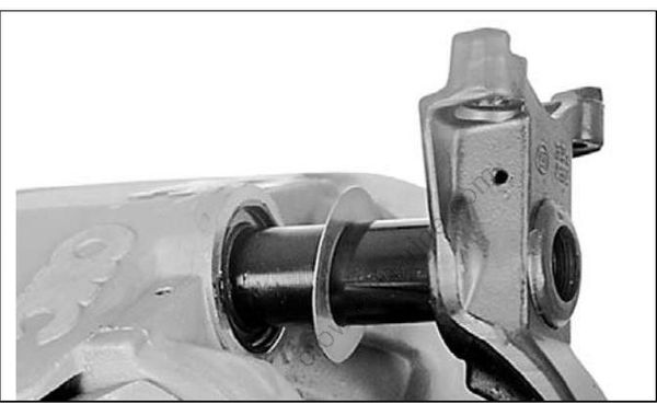
Install the steering shaft keeper. Apply Locquic Primer and Nut Lock to the splines of the steering shaft and lower mount bracket.
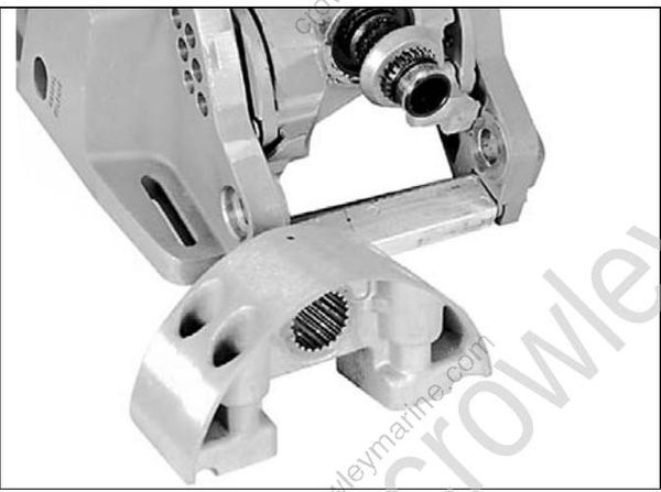
Install the lower mount bracket and a new locking nut with its unstaked side facing the mount bracket. Align the bracket with the steering arm and tighten the nut to a torque of 130 to 150 ft. lbs. (176 to 204 N·m).
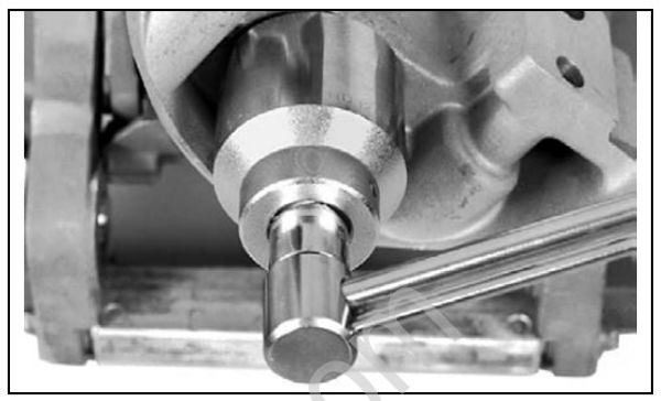
Fill the swivel bracket with Triple-Guard grease through the grease fitting on the bracket’s port side. Lubricate the tilt tube, swivel bracket, and stern brackets through the two forward grease fit tings.
Install the exhaust housing. Refer to Exhaust Housing Installation on p. 243.
