

REMOVAL
Protect against hazardous fuel spray. Before starting any fuel system service, carefully relieve fuel system pressure. Refer to Relieving Fuel System Pressure on p. 184.
To prevent accidental starting while servicing, disconnect the battery cables at the battery.
IMPORTANT: Reinstall all fasteners, nuts, and bolts in their holes as the engine components are removed. This will simplify identification and assembly.
Remove the fuel hose and oil hose from the fittings.
Disconnect power trim/tilt switch.
Loosen the lower engine cover retaining screws. Remove one lower cover half at a time.
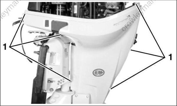
- Lower cover screws
Disconnect diagnostic connector from clip and remove flywheel cover.
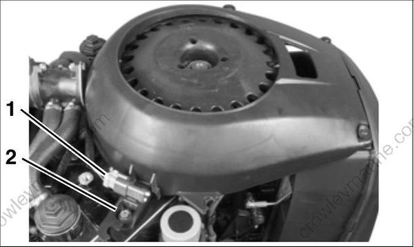
- Diagnostic connector
- Flywheel cover screw
Loosen air silencer screws. Twist and remove air temperature sensor from air silencer. Remove air silencer.
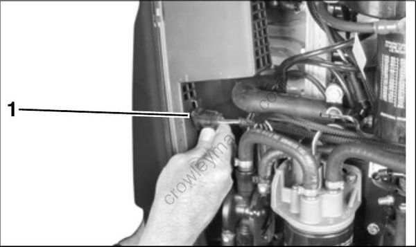
- Air temperature sensor
Remove water hoses and exhaust back pressure hose from adapter.
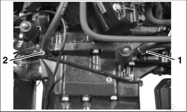
- Cooling hose (to exhaust plenum)
- Cooling hose (from vapor separator)
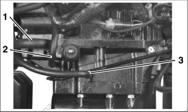
- Cooling hose (to exhaust plenum)
- Exhaust back pressure hose (to EMM)
- Cooling hose (from block)
Disconnect power trim/tilt connections from engine harness.
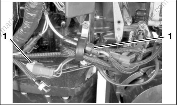
- Trim/tilt connectors
Remove trim/tilt harness from clamp.
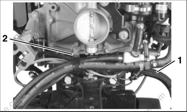
- Trim harness
- Clamp
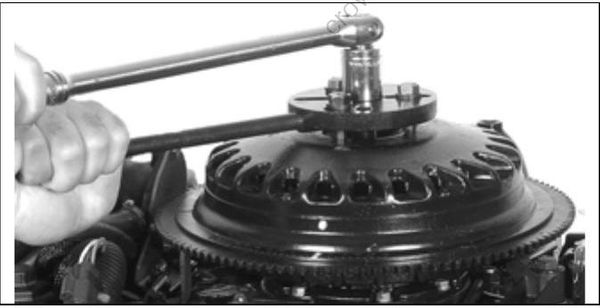
Use Flywheel Holder, P/N 771311, and a 1 7/16 in. socket to remove the flywheel retaining nut.
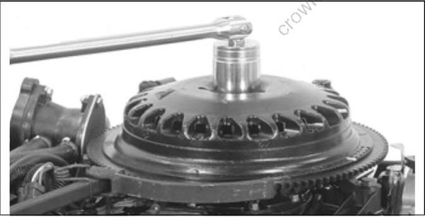
Assemble pieces of Universal Puller Set, P/N 378103, and remove the flywheel. See FLYWHEEL SERVICING on p. 152.
Remove shift rod pin.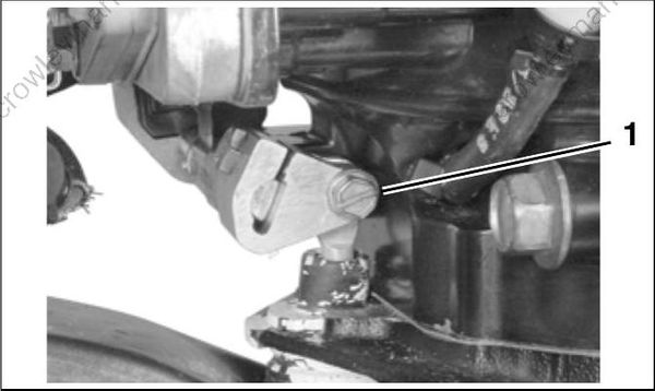
- Shift rod pin
On each side, remove the powerhead retaining screws and nuts.
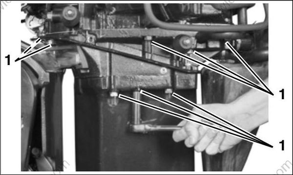
- Screws and nuts
Remove the rear powerhead nut.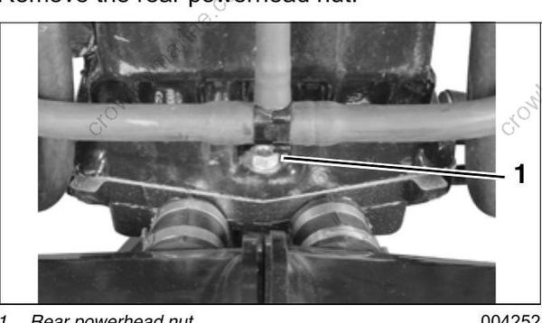
- Rear powerhead nut
Securely fasten Lifting Fixture, P/N 396748, to crankshaft threads and lift powerhead with a suitable hoist.
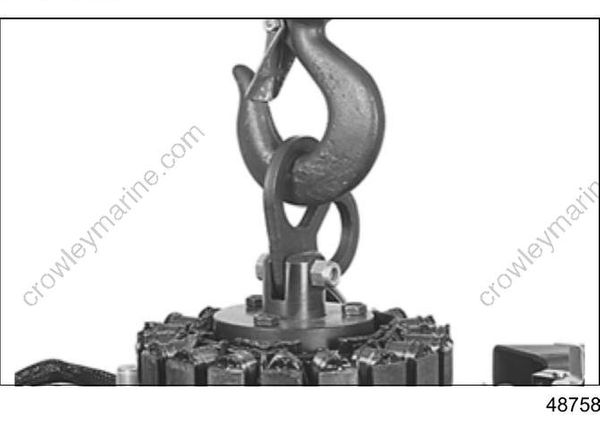
Remove all fuel, ignition, and electrical components from the powerhead. To simplify reassembly and wiring installation, lay out the various screws and clamps in the order of their proper location.
