

Test Procedure
Make sure red and black wires are connected to 12 V battery power supply.
Set voltmeter to 12 VDC scale. Connect test leads to terminals “A” and “B” of TNT motor connector.
Use a wire jumper to alternately connect B+ to terminals “1” and “2” of tilt and trim switch connector. The meter must indicate battery voltage (12 V) with B+ connected to either terminal.
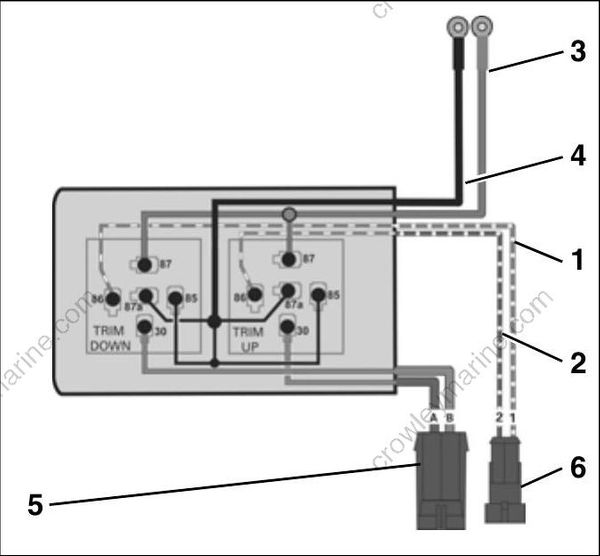
Tilt and Trim Module Diagram
- Green/white wire
- Blue/white wire
- B+, red wire
- B–, black wire
- TNT motor connector
- TNT switch connector
FLYWHEEL SERVICING
Weak flywheel magnets can cause low alternator output and affect outboard performance. Weak flywheel magnets can also cause low readings on ignition test equipment such as the peak-reading voltmeter, which might cause unnecessary replacement of ignition components.
An accurate test of alternator output can help determine the flywheel’s condition. Refer to CHARGING SYSTEM TESTS on p. 142.
Removal
To prevent accidental starting while servicing, remove emergency stop lanyard and disconnect the battery cables at the battery.
Remove flywheel nut using Flywheel Holder, P/N 771311, or equivalent, and a 1 7/16 in. socket. Discard flywheel nut.
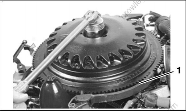
- Flywheel holder
Apply Moly Lube grease to the threads of the puller pressing screw, P/N 307637, and the center hole of the crankshaft.
Assemble the following components from Universal Puller Set, P/N 378103:
- Body, P/N 307636
- Screw, P/N 307637
- Handle, P/N 307638
- Three screws P/N 309492
- Three washers, P/N 307640
Put the puller on flywheel with body flat side up. Attach the puller body with the three shoulder screws and washers. Hold puller body with handle, and tighten pressing screw until flywheel releases. Turn the center screw and lift the fly wheel off of the crankshaft.
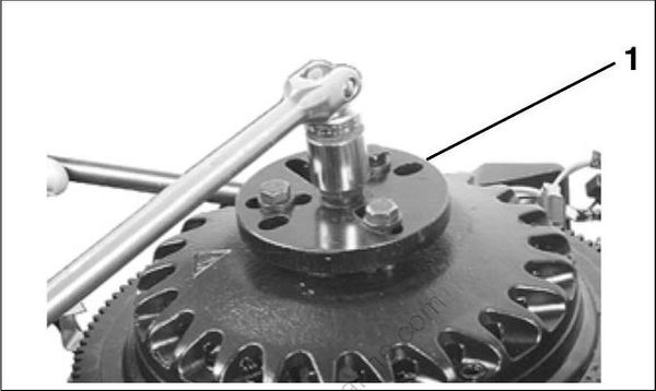
- Universal puller
Installation
Install the outer edge of flywheel key parallel with centerline of crankshaft.
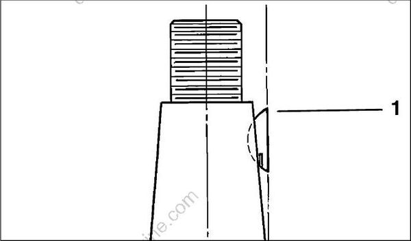
- Flywheel key
Thoroughly clean the crankshaft and flywheel tapers with Cleaning Solvent™ and let dry.
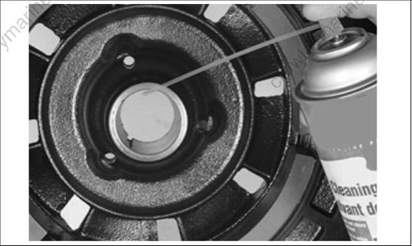
Apply a thin, even coat of Nut Lock™ to the inside taper of the flywheel.
DO NOT over apply Nut Lock on flywheel taper. This prevents Nut Lock from migrating into upper seal of crankshaft.
Align the flywheel keyway and install the flywheel. Coat the threads of a new flywheel nut with Gasket Sealing Compound. Install the nut and torque to 140 to 160 ft. lbs. (190 to 217 N-m).
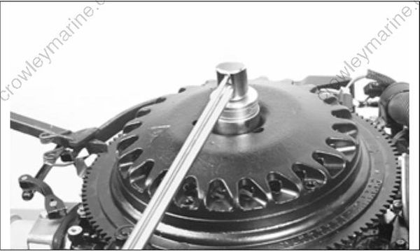
Perform the timing verification procedure after flywheel removal or replacement. Refer to TIMING ADJUSTMENTS on p. 154.
