

Voltage Testing
Use a digital multimeter to check voltages. Identify all wiring and circuits prior to performing any volt age tests. Refer to Wiring Diagrams and descriptions of the various systems for specific information on each circuit.
55 V Circuits
All 55 V circuits are supplied 12 V when the key switch is ON, the EMM is powered up, and the outboard is not running.
Stator output supplies 55 VAC to the rectifier circuits of EMM once the outboard is running. The initial cranking voltage is 30 V or higher and increases to 55 V when outboard is running.
Ignition Circuit
Ignition voltage displayed on the engine Monitor screen of the diagnostic software will have approximately 0.1 V when the key switch is ON, the EMM is powered up, and the outboard is not running (electric start models). This voltage increases to 130 V to 220 V with the outboard running.
Perform voltage tests on all related circuits and compare voltage readings. Check voltages while Dynamic Tests are activated.
Identify erratic or lower than expected voltage readings. Determine if the voltage source or the wiring and connections of the circuit are the problem.
START CIRCUIT
The start circuit provides the required current to the starter motor and associated electrical circuits.
Electric Starter Operation
The starter must engage and turn the flywheel. A minimum cranking speed of 300 RPM must be achieved for the outboard to start.
Optimum starter performance is achieved by providing:
Proper battery capacity (640CCA)
Cables capable of transferring the amperage
Low resistance battery and cable connections
A solenoid capable of switching the current
These “high amperage” start circuit components provide the battery current required to crank and start the outboard (electric start models). Check the quality and condition of the following:
12 V Marine Battery
Battery type, capacity, and condition
Condition of battery posts, terminals, and connections
Battery switch type, capacity, and connections
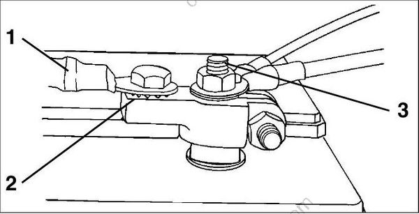
Main battery cable
Star washer
Battery post
Refer to Battery Installation on p. 34 for battery, terminal, and cable requirements.
Starter Solenoid
Starter solenoid and connections
Starter solenoid ground, terminal “B”
Starter cable (solenoid to starter motor)
12 V from solenoid terminal (POS) and engine harness (red wire) to 10 A fuse
Starter Motor and Drive Gear
Starter motor operation, refer to ELECTRIC STARTER SERVICING on p. 145.
Starter bendix operation.
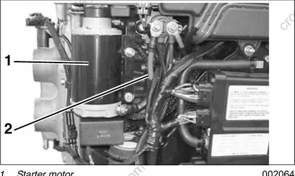
Starter motor
Starter cable
Starter Solenoid Activation
Solenoid Wiring
The positive (B+) battery cable connects to the large front terminal of the starter solenoid. This terminal also provides the 12 V power supply to the engine harness (red wire) and the 10 A fuse. The red/purple wire from the fuse holder (10 A) provides 12 V to terminal “B” of key switch.
The negative (B–) battery cable connects to the ground stud on the starter housing.
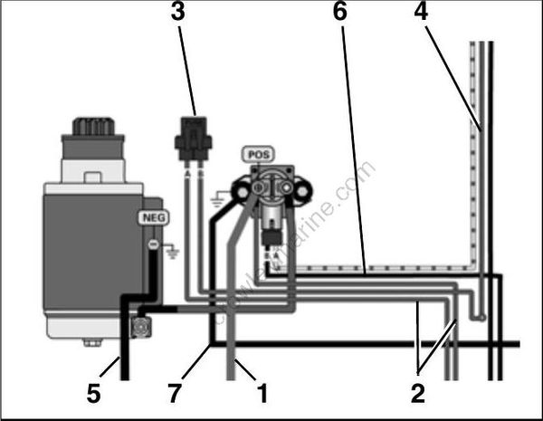
Positive (B+) battery cable (Red)
Engine harness red wire
10 A fuse
Engine harness red/purple wire
Negative (B–) battery cable (Black)
Solenoid ground (Black)
Engine harness ground (Black)
Key Switch, START Position
Switches 12 V to terminal “S” of key switch and 12 V is applied to neutral safety switch.
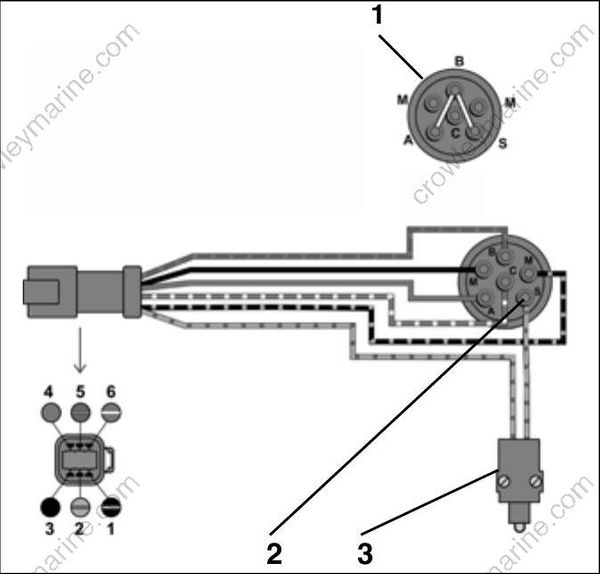
Ignition switch, START position – Continuity between terminals “B” and “A”; “B” and “S”
Terminal “S”, 12 V
Neutral safety switch
Neutral Safety Switch (Remote Control)
Terminal “S” of the key switch provides 12 V (yellow/red) to the neutral safety switch (key switch in START position).
A depressed or activated neutral safety switch (in remote control) provides 12 V to the engine wire harness yellow/red wire (key switch in START position) and terminal “A” of starter solenoid.
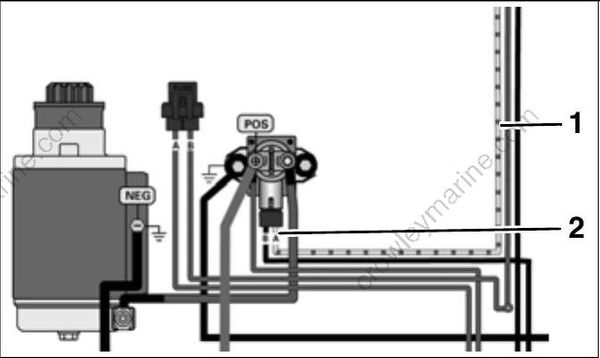
Yellow/red wire
“A” terminal
