

IGNITION OUTPUT
DANGER
The electrical system presents a serious shock hazard. Allow outboard to sit for two minutes after running before handling capacitor or 55 V electrical components. Failure to handle capacitor properly can result in uncontrolled electrical discharge and possible electrical shock to humans. DO NOT handle primary or secondary ignition components while outboard is running or flywheel is turning.
Wiring Inspection
Visually inspect all wiring, connections, and grounds.
Use an ohmmeter to perform resistance tests on all ground circuits and connections. Ohmmeter readings should be approximately 0.0 Ω.
Check that main engine wire harness ground stud has continuity to the cylinder/crankcase.
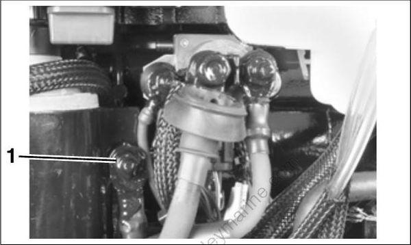
- Ground stud
Make sure battery is fully charged.
Clean or repair all ground circuits, wiring, and connections as needed. Refer to ELECTRICAL CONNECTIONS on p. 104.
Ignition Voltage
Use the Evinrude Diagnostics Software program to check ignition voltage to the primary ignition circuit(s). Check the EMM’s ignition voltage to the primary circuits of the ignition coils on the engine Monitor screen.
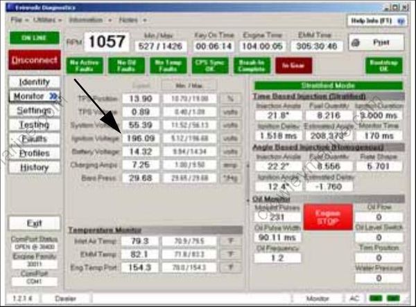
Engine Monitor Screen, Ignition Voltage
Results:
“KEY ON” approximately 5 V, Ignition voltage is GOOD, check voltage with outboard “running”. Refer to Static Spark Test on p. 116.
“KEY ON” no voltage, check system voltage to EMM. Refer to System Voltage on p. 116.
“RUNNING” 200 V ± 10, Ignition voltage is GOOD. Refer to Static Spark Test on p. 116.
“RUNNING” less than 200 V ± 10, check stator output to EMM. Refer to System Voltage on p. 116 and Stator Tests on p. 129.
Low or no voltage on EMM ignition circuit:
- Check system voltage (55 V) input to ignition circuit on pins 3 and 4 of EMM J1-B connector.
System Voltage
The ignition module of the EMM is powered by input voltage on pins 3 and 4 of EMM J1-B connector.
Use the engine Monitor screen of the Evinrude Diagnostics Software program to check system voltage.
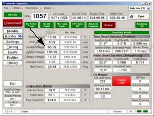
Engine Monitor Screen, System Voltage
Results:
“KEY ON” Approximately 1 V less than battery voltage, system voltage is GOOD.
“KEY ON” NO voltage, check 12 V power to EMM. Repair connection or wiring.
“RUNNING” 55 V ± 2, system voltage is GOOD.
“RUNNING” less than 55 V ± 2, check stator output to EMM. Repair connection or wiring. Possible faulty stator or EMM. Refer to Stator Tests on p. 129.
IMPORTANT: EMM must be ON for voltage to be present on the 55 V alternator output circuit. This output supplies all 55 V circuits on the engine, including the ignition module of the EMM. Power is normally supplied to the EMM when the key switch is ON. Switched B+ (12 V) is supplied to the engine wire harness. Voltage enters the EMM at pin 10 (purple) of the EMM J1 B connector.
Static Spark Test
Perform the static spark test using the Evinrude Diagnostics Software program and a timing light.
IMPORTANT: DO NOT use a spark checker tool with E-TEC models. Radio Frequency Interference (RFI) generated by the arcing current can cause erratic behavior in the EMM.
The outboard must NOT be running and the emergency stop switch lanyard must be installed.
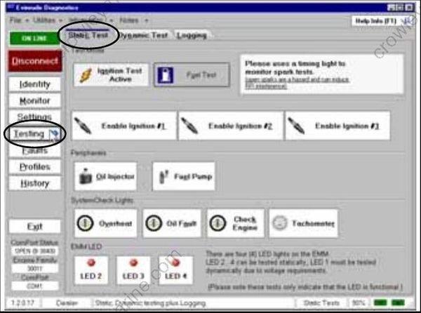
Static Tests Screen
Connect timing light pickup to primary and then secondary circuit of the ignition circuit being activated. Activate one circuit at a time and observe timing light strobe for consistent flash.
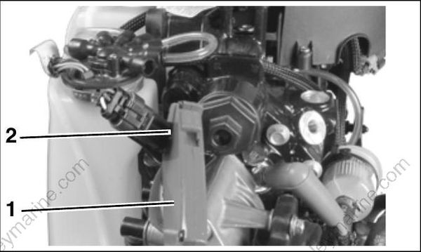
Timing light pick-up
Ignition coil primary wire (orange)
Results:
GOOD spark control on all cylinders and out board runs, refer to Running Ignition Tests on p. 117 and Dynamic Tests on p. 110.
NO spark control on one or more cylinders, note cylinders. Refer to Ignition Primary Circuit Resistance Test on p. 118 and Ignition Coil Tests on p. 128.
Running Ignition Tests
The purpose of this test is to isolate ignition sys tem malfunction. This test should be used in con junction with other ignition system tests to identify component failures. This test provides limited information. Use the findings of this test to eliminate ignition system components. A thorough understanding of the outboard’s ignition system is required.
Monitor Voltage Outputs
Use the Evinrude Diagnostics Software program to monitor system voltage (55 V) and ignition volt age (200 V).
- Voltage readings at a specific speed (RPM) should be steady.
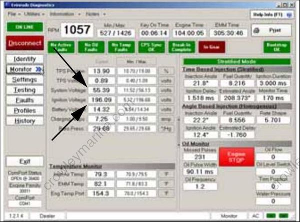
Engine Monitor Screen, System and Ignition Voltage
Results:
Low voltages: refer to System Voltage on p. 116 and Ignition Voltage on p. 115.
Monitor Ignition Output with Timing Light
Use a timing light to monitor the spark signal through each of the high tension spark plug wires.
Start outboard and observe the timing light’s strobe. Look for a consistent flash and only one flash per revolution. The strobe of the timing light should be consistent or the same for each cylinder’s ignition output.
IMPORTANT: Test on primary circuit if strobe from secondary circuit appears faulty.
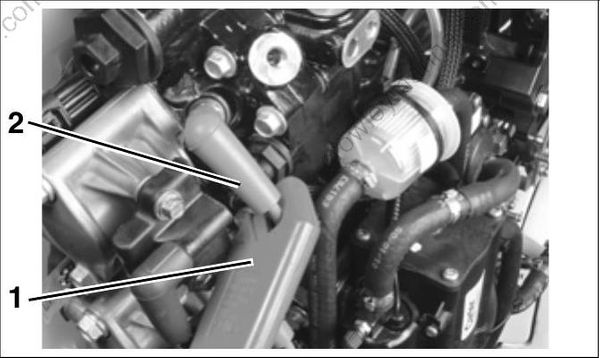
Timing light pick-up
Spark plug lead
Results:
Steady voltage and strobe:
- Inspect or replace spark plugs, check fuel system performance, and/or eliminate the possibility of internal engine damage.
Voltages are steady, engine misfires:
- Check CPS resistance, check ignition voltage while problem is occurring. Refer to Ignition Primary Circuit Resistance Test on p. 118 and Ignition Coil Tests on p. 128.
Voltages fluctuate, engine misfires:
- Inspect condition of battery and connections, test capacitor, and check all ground connections. Refer to System Voltage on p. 116, Ignition Voltage on p. 115, Ignition Primary Circuit Resistance Test on p. 118, and Ignition Coil Tests on p. 128.
IMPORTANT: If a running problem occurs at about 1200 RPM, the outboard may be in S.A.F.E. Refer to Conditions that initiate S.A.F.E. on p. 92.
Ignition Primary Circuit Resistance Test
Disconnect the battery cables at the battery.
Calibrate ohmmeter to low ohms scale.
With key switch OFF, remove the EMM J1-B connector and measure resistance of each primary circuit. Note resistance reading between each primary wire and ground. Refer to engine wiring diagram.
Ignition Primary Circuit Resistance
0.090 ± 0.005 Ω.
IMPORTANT: A reading of less than 2 ohms is acceptable. Make sure meter is calibrated to read 1 ohm or less.
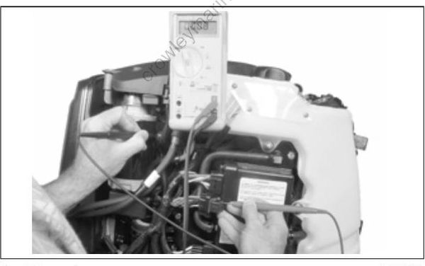
Ohmmeter
J1-B EMM connector
Red meter lead, with pin adapter
Black meter lead to ground
Results:
Primary circuit resistance reading is higher than 5 Ω:
Repair primary circuit wiring or coil grounds as needed and retest.
Replace faulty coils or wiring.
Primary circuit resistance reading less than 5 Ω or within specification and EMM ignition output volt age is 130 V or higher:
- Refer to Secondary Winding Resistance Test on p. 128. Repair high tension spark plug lead or replace ignition coil and/or high tension spark plug lead assembly.
Crankshaft Position Sensor (CPS) Test
Use the Evinrude Diagnostics Software program to check RPM reading. An RPM display higher than zero indicates a CPS signal to the EMM. Cranking RPM is typically 200 RPM or higher.
Observe Engine RPM and Power ON Time dis play fields of the engine Monitor screen. “ON Time” should be continuous and should not reset unless the key switch is turned OFF or power to the EMM is interrupted.
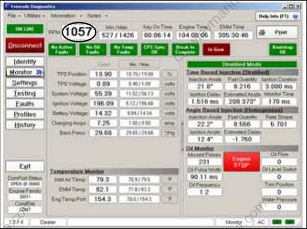
Engine Monitor Screen, Engine RPM display
Check CPS resistance (560 Ω ± 10%).Make certain ohmmeter is calibrated properly. Refer to Crankshaft Position Sensor (CPS) Test on p. 127.
