

Key Switch, START Position
Key switch START:
- Switches 12 V to terminal “S” of key switch and to the neutral safety switch (in remote control).
- A closed neutral safety switch provides 12 V to the engine wire harness yellow/red wire and solenoid (terminal “A”).
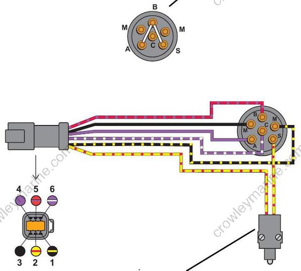
- Ignition switch, START position – Continuity between terminals “B” and “A”; “B” and “S”
- Terminal “S”, 12 V
- Neutral safety switch
ELECTRIC START TESTS
Starter Solenoid Test
Disconnect the B+ (POS) battery cable at the battery.
IMPORTANT: Disconnect all wiring from solenoid terminals before proceeding with this test.
Use a digital multi meter to measure resistance.
Put one meter lead on the starter positive (+) cable terminal and the other lead on the battery positive (+) cable terminal:
- Meter must not show continuity (high reading).
- If meter shows continuity (low reading), replace the solenoid.
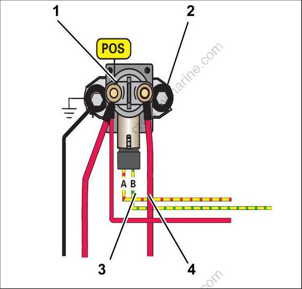
- Battery positive cable (B+) terminal
- Starter positive (+) cable terminal
- “A” terminal (yellow/red)
- “B” terminal (yellow/green)
Apply B+ to terminal “A” of solenoid and ground (NEG) to terminal “B” of solenoid. Measure resistance between the starter positive (+) cable terminal and the positive battery (+) cable terminal.
- The solenoid must close with an audible click.
- Meter must show continuity (low reading).
- If meter shows no continuity (high reading), replace the solenoid.
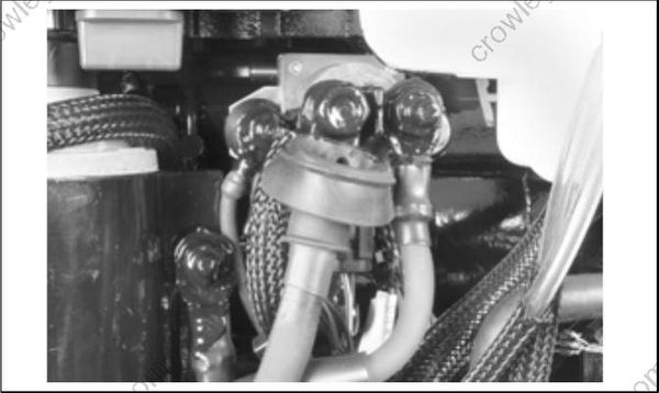
After re-installing the solenoid, coat all wires and terminals with Black Neoprene Dip_.
No Load Current Draw Test
No Load Current Draw Test
Securely fasten starter in a vise or suitable fixture before proceeding with this check.
Use a battery rated at 500 CCA (60 amp-hr) or higher that is in good condition and fully charged. Use an inductive ammeter or connect a 0 to 100 amp ammeter in series with a heavy jumper between the battery positive (+) terminal and the starter positive (+) terminal.
Fluke model 334 or 336, Snap-On model MT110 or EETA501, and various other ammeters should be available through local tool suppliers. Attach or hold a vibration tachometer, such as a Frahm† Reed tachometer, to the starter.
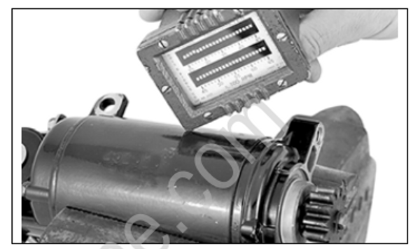
Complete the circuit with a heavy jumper between the battery negative (–) terminal and the starter frame.
Monitor the starter RPM and current draw.
- At 10,500 RPM the ammeter should show a maximum of 30 A.
