

Propshaft, Gear and Shifter Installation
IMPORTANT: Make no dry assemblies. Lubricate all bearings, shafts, and gears with gearcase lubricant.
Oil and place the forward bearing cone and roller assembly in the forward bearing cup.
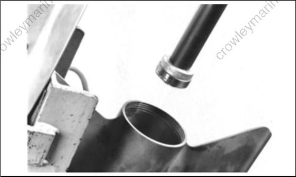
Install the small thrust washer with the chamfered inside diameter facing the pinion gear. Oil and install the thrust bearing. Install the large thrust washer with chamfered outside edge facing up.
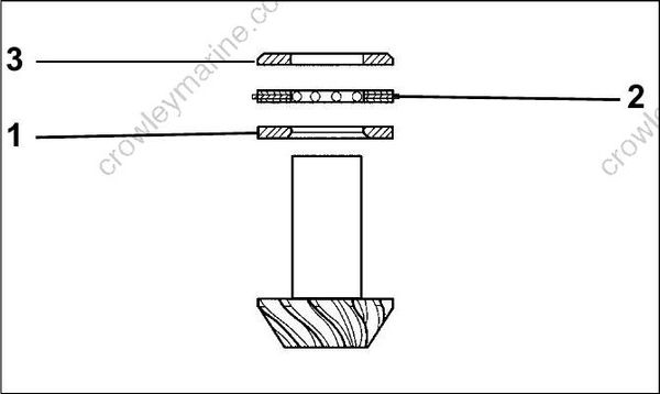
- Small thrust washer, chamfered inside diameter
- Thrust bearing
- Large thrust washer, chamfered outside edge
Use a right angled rod to install the pinion assembly in the gearcase.

Place the forward gear into the gearcase.
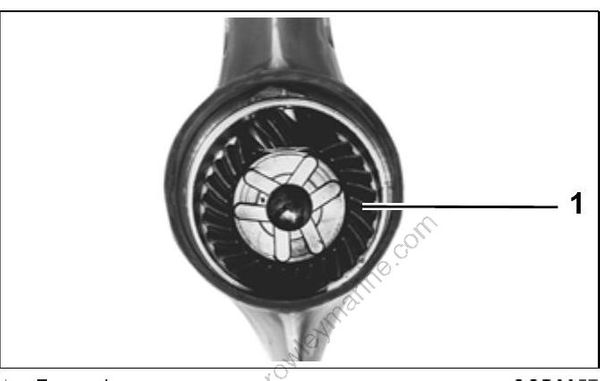
- Forward gear
Install the shifter cradle on clutch dog. Grooved end of clutch dog must face forward gear end of the propeller shaft.
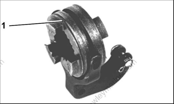
- Grooved end
IMPORTANT: Apply Needle Bearing grease to clutch dog and shifter cradle to hold in place while assembling.
Install the shifter cradle and clutch dog in the gearcase using long-nose pliers.
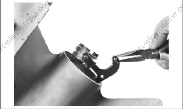
Apply Triple-Guard grease to a new pivot pin O-ring. Install O-ring on the pivot pin. Apply Nut Lock to threads of the pin. Align hole of shifter lever with hole in gearcase. Install and tighten pivot pin to a torque of 60 to 84 in. lbs. (7 to 9.5 N·m).
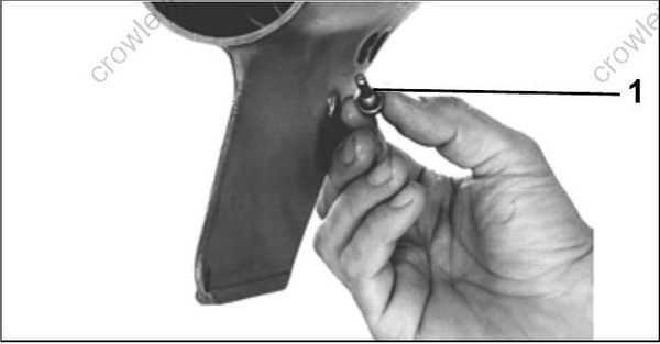
- Pivot pin
Wear safety glasses for eye protection. Detent balls can pop out with great force.
Slide the Shift Detent Sleeve, P/N 328081, over the propeller shaft. Align slot in the tool with hole in the propeller shaft.
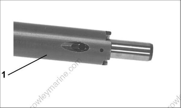
- Shift detent sleeve
Insert one detent ball, then the spring, then the other detent ball. Push down on the ball and slide the tool back until you feel the ball slip into the detent.
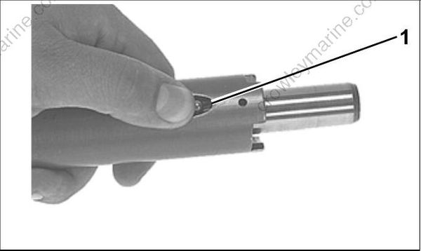
- Detent ball
Install the propeller shaft and detent tool in gear case. Make sure the following occurs:
- Propeller shaft must engage forward bearing.
- Tool ramps must engage clutch dog ramps.
- Hold tool firmly against clutch dog.
- Gently tap propeller shaft with a rawhide mallet to seat detent assembly.
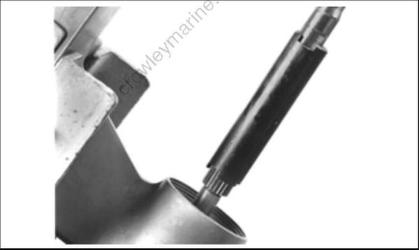
Remove detent tool. Slide the reverse gear down the propeller shaft and into the gearcase.
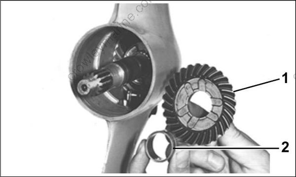
- Reverse gear
- Bushing
Coat the reverse gear bushing with oil. Slide the bushing down the propeller shaft, seating the bushing into the reverse gear.
Holding the shifter yoke a with long-nose pliers, install the yoke at a tilted position, locating top of yoke into upper gearcase cavity.
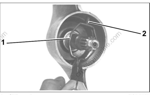
- Shifter yoke
- Top of yoke
Engage the shifter yoke hook onto the shifting lever clevis pin in bottom of the gearcase cavity.
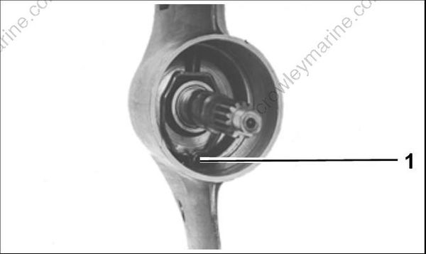
- Shifter yoke hook
Apply Triple-Guard grease to threads of lower shift rod and install into gearcase through the water intake opening and engage the shifter yoke.
Thread the shift rod into the shifter yoke until the rod bottoms in the yoke.
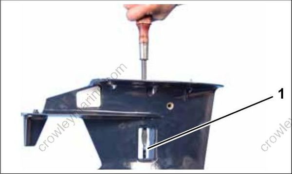
- Lower shift rod
Propeller Shaft Bearing Housing Installation
Slide the retainer plate down the propeller shaft and into the gearcase with tab facing down.
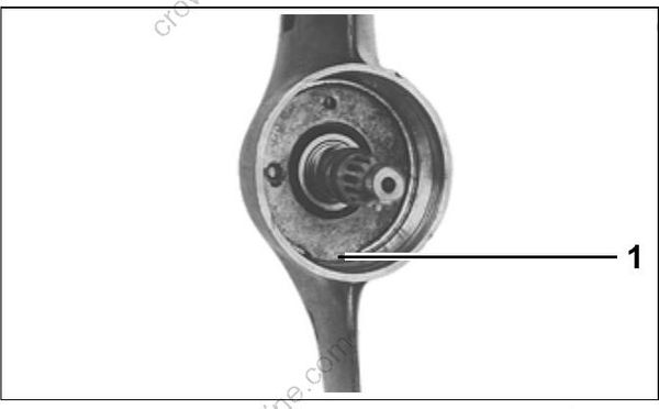
- Tab, retainer plate
Wear safety glasses and proceed with care to avoid unsnapping the ring from the pliers.
Using Retaining Ring Pliers, P/N 331045, install the retaining ring into groove in gearcase with sharp outside edge facing aft.
IMPORTANT: The retaining ring is under extreme pressure during installation. Make sure that the ring is seated in groove.
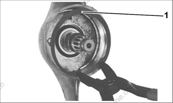
- Retaining ring
Thread one Guide Pin, P/N 383175, into the retainer plate.
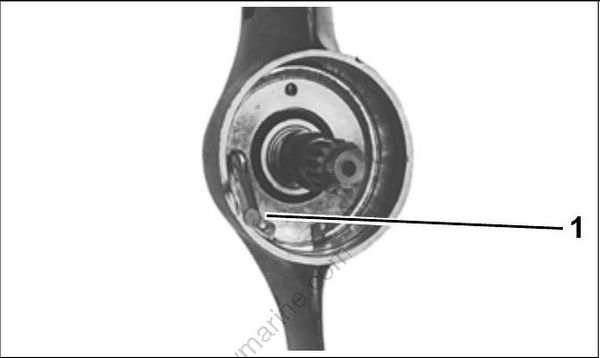
- Guide pin
Use Needle Bearing grease to temporarily hold the reverse gear thrust washer on the back of the propeller shaft bearing housing.
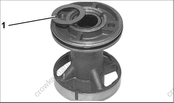
- Reverse gear thrust washer
Lightly apply Gasket Sealing Compound to the aft support flange of the bearing housing. Align the propeller shaft bearing housing on the guide pin with the word "UP" toward the top.
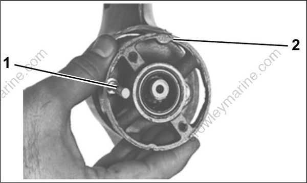
- Guide pin
- “UP
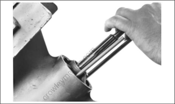
Using a brass punch and a mallet, seat the bearing housing in the gearcase.
Place new O-rings on the bearing housing retaining screws. A Apply Gasket Sealing Compound to the O-rings and threads of the screws.
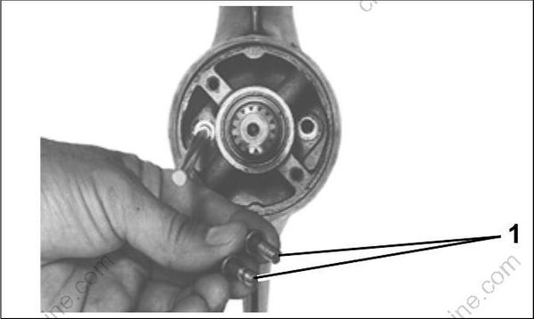
- Screws
Install one screw in the bearing housing. Remove the guide pin and install the second screw. Tighten screws to a torque of 124 to 142 in. lbs. (14 to 16 N·m).
Apply Adhesive 847 to the bottom of a new exhaust seal assembly and install it into the slot in the gearcase.
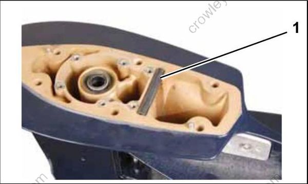
- Seal assembly
To complete gearcase assembly, refer to:
• WATER PUMP SERVICE on p. 274
• GEARCASE LEAK TEST on p. 271
• GEARCASE REMOVAL AND INSTALLATION on p. 272
• Gearcase Lubricant on p. 65
• Propeller Hardware Installation on p. 56
• Trim Tab Adjustment on p. 58.
During break-in period of a reassembled gear case, change the gearcase lubricant between 10 to 20 hours of operation.
