

Service Manual
35 to 40 ft. lbs. (47 to 54 N•m). For adjustment, refer to Trim Tab Adjustment on p. 68.
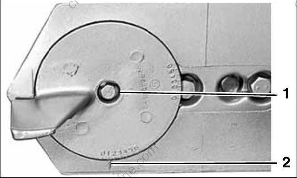
- Trim tab screw
- Index mark
IMPORTANT: Standard rotation and counter rotation trim tabs must not be interchanged. This would result in inadequate cooling water supply to the propeller hub.
Place the shift rod in the shift rod lever. Install the retaining pin and washer. Tighten pin to a torque of 60 to 84 in. lbs. (7 to 9.5 N•m).
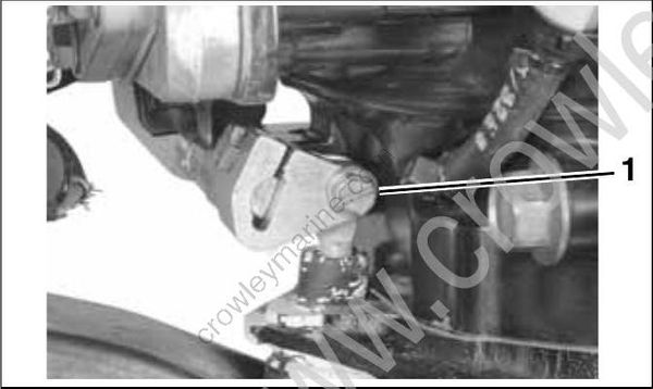
- Shift rod screw
To prevent loss of operator control, check for proper shifting operation and adjust, if necessary.
IMPORTANT: During break-in period of a reassembled gearcase, change the gearcase lubricant between 10 to 20 hours of operation.
WATER PUMP SERVICE
Disassembly
Rotate the driveshaft counterclockwise to unlock the impeller cam. Remove the four impeller housing screws.
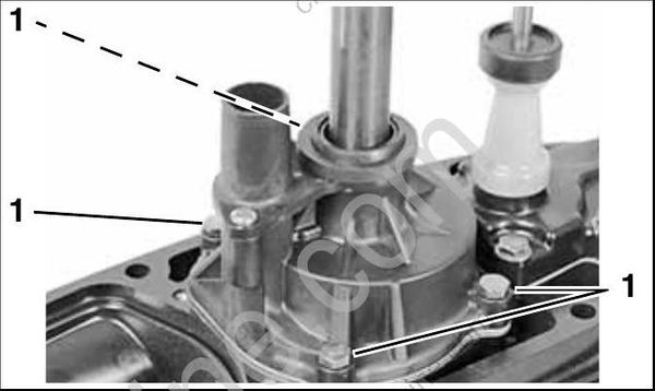
- Screws
Slide the water pump off the driveshaft. Remove the impeller drive cam, O-ring, impeller plate, and gasket. Discard the gasket.
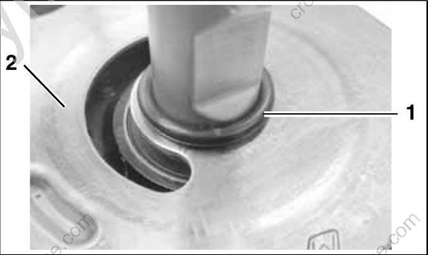
- O-ring
- Impeller plate
Remove all the parts from the housing.
Inspection
Check impeller for overheating, hub separation, and other wear or damage.
Check liner and wear plate for scoring, distortion, and impeller material transfer.
Inspect the housing for cracks or melting.
Assembly
Apply a drop of Adhesive 847 in the seal ring groove at each of the four ribs.
IMPORTANT: Do not allow any adhesive to get into the air bleed groove in the impeller housing. If this groove is blocked by adhesive, the pump will lose its prime and will not pump water.
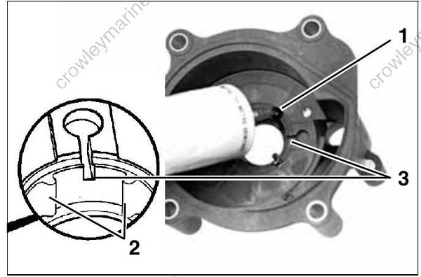
- Seal ring groove
- Ribs
- Air bleed groove
Install the O-ring in groove in the impeller housing.
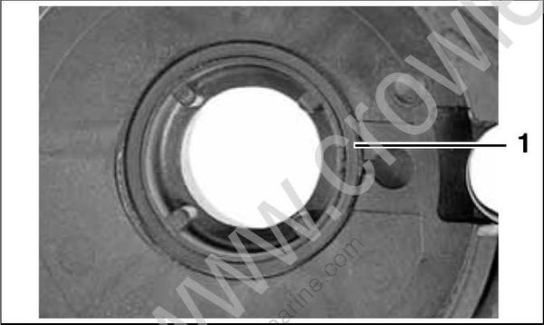
- O-ring
Lightly coat the exterior of the impeller cup with Gasket Sealing Compound. Install the cup in the impeller housing.
Install the water tube grommet with the inside taper facing up.
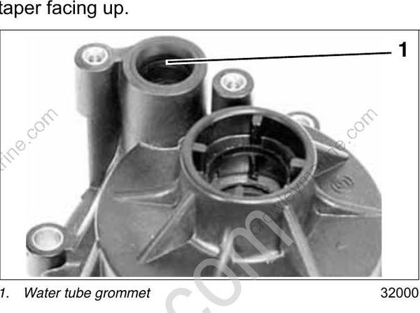
- Water tube grommet
Install the impeller housing cover and tighten screws to a torque of 24 to 36 in. lbs. (3 to 4 N•m).
Apply Adhesive 847 to flat side of the impeller housing grommet. Install the grommet, flat side down.
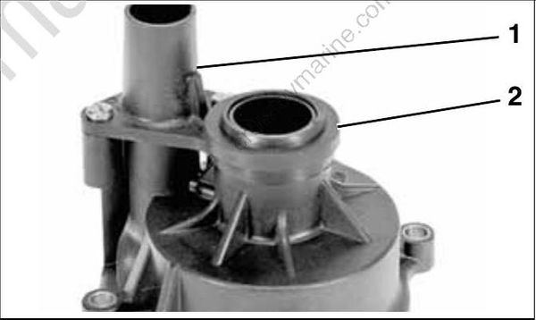
- Impeller housing cover
- Impeller housing grommet
Lightly coat the liner with Triple-Guard grease. With a counterclockwise rotation, install the impeller into the liner with slot for impeller cam facing out.
Run a thin bead of Adhesive 847 in the seal groove, and install the special shaped O-ring seal.
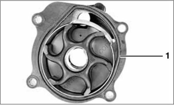
- O-ring
Apply Gasket Sealing Compound to both sides of a new impeller plate gasket. Install the gasket and impeller plate.
Apply Triple-Guard grease to a new impeller O ring. Slide the O-ring down the driveshaft and slide half way over installed drive cam to temporarily hold cam in place.
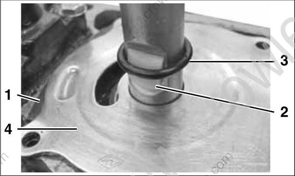
- Impeller plate gasket
- Impeller plate
- O-ring
- Drive cam
The sharp edge of the cam is the leading edge in clockwise rotation.
Slide the water pump down the driveshaft. Align impeller slot with the impeller cam. Rotate the driveshaft to engage the impeller cam with the impeller, and slide water pump down over cam. Be sure impeller cam does not fall out of position.
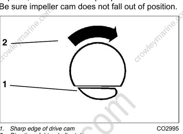
- Sharp edge of drive cam
- Direction of driveshaft rotation
IMPORTANT: Make sure the impeller engages the impeller cam. Serious powerhead damage will result if impeller cam is not in place.
Align the impeller housing with the gearcase. Apply Gasket Sealing Compound to threads of the four impeller housing screws. Install the screws and tighten to a torque of 60 to 84 in. lbs. (7 to 9.5 N•m).
25 in. and 30 in. Models
Place water tube spacer with grommet on the impeller housing cover.
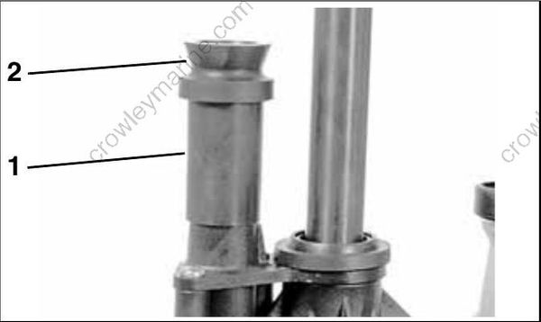
TYPICAL
- Spacer
- Grommet
IMPORTANT: Before installing gearcase, shift rod adjustment MUST be checked. Refer to SHIFT ROD ADJUSTMENT on p. 281.
