

Final Powerhead Assembly
Install the reed plate and throttle body assemblies. Refer to Intake Manifold Service on p. 173.
Install oil recirculating hoses and check valves. Refer to OIL RECIRCULATION DIAGRAM on p. 180, or POWERHEAD VIEWS on p. 224.
Install thermostat and pressure valve assembly. Refer to THERMOSTAT AND PRESSURE RELIEF VALVE SERVICING on p. 198.
Install electrical harness.
Install fuel injectors and ignition coils. Refer to Fuel Injector Vapor Separator and Fuel Injector Service on p. 168.
IMPORTANT: All injectors must be installed in their original location. Improper injector installation can result in powerhead failure.
Install stator and flywheel. Refer to FLYWHEEL AND STATOR SERVICING on p. 141.
Install fuel pump assemblies, fuel manifolds, and filter. Refer to FUEL COMPONENT SERVICING on p. 166.
Install the oil tank and oil injection hoses. Refer to Oil Tank Assembly on p. 189.
Install the electric starter. Refer to Starter Installation on p. 149.
Install EMM. Refer to EMM SERVICING on p. 104.
Install spark plugs. Refer to Spark Plug Indexing on p. 77.
To prevent fire and explosion hazard, make sure all electrical and ignition wiring is routed and clamped in original positions.
POWERHEAD INSTALLATION
Powerhead Mounting
Coat the driveshaft splines with Moly Lube. Do not apply lubricant to end of driveshaft.plines.
Be sure water tube is placed in upper and lower grommets.
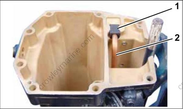
- Water tube
- Grommet
Slowly lower powerhead onto exhaust housing. If necessary, rotate flywheel in a clockwise direction to align crankshaft and driveshaft splines.
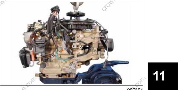
Apply Triple-Guard grease to the threads of the powerhead screws.
Loosely install all powerhead screws before tightening:
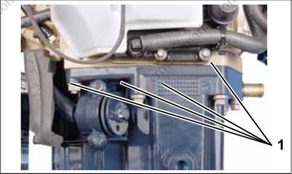
- Powerhead screws
Tighten the eight powerhead screws to a torque of 18 to 20 ft. lbs. (24 to 27 N·m) in the sequence shown.
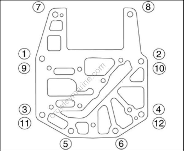
Large screw torque sequence, 1 – 12
IMPORTANT: Retighten powerhead mounting screws after outboard has been run at full operating temperature and allowed to cool.
Place the upper shift rod in the shift rod connector. Install the retaining screw and lock washer. Tighten screw to a torque of 60 to 84 in. lbs. (7 to 9.5 N·m).
Install water screens.
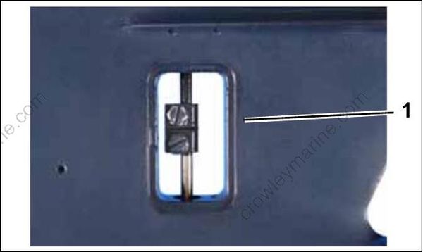
- Shift rod screw
Check shift linkage adjustment. Refer to Shift Linkage Adjustment on p. 223.
IMPORTANT: Make sure the gearcase shifts solidly into both forward and reverse and that propeller shaft spins freely in neutral.
Connect the power trim connectors. Secure cables in clamps.
Install recoil starter ratchet and housing on outboard. Refer to RECOIL STARTER INSTALLATION on p. 314.
Install the lower engine covers. Refer to Lower Cover Installation on p. 83.
Shift Linkage Adjustment
Adjust shift linkage as follows:
Shift engine into neutral.
Make sure shift lever detent is in neutral position.
Center the neutral switch on shift lever detent.
Tighten neutral switch bracket screws to a torque of 35 to 60 in. lbs. (4 to 6.8 N·m).
Loosen two shift lever screws.
Remove one shift lever screw. Clean and apply Nut Lock to threads.
Adjust the shift lever parallel to the crankcase flange as shown. Reinstall the shift lever adjustment screw.
Hold shift lever in positiion and tighten screw to a torque of 80 to 106 in. lbs. (9 to 12 N·m).
Remove remaining shift lever screw. Clean screw and apply Nut Lock to threads. Reinstalll and tighten screw to a torque of 80 to 106 in. lbs. (9 to 12 N·m).
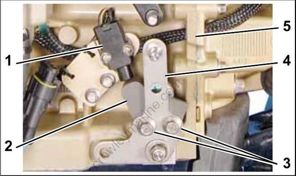
- Neutral switch
- Shift lever detent
- Shift lever screws
- Shift lever
- Crankcase flange
Pre-Service Adjustments
After installing a new or rebuilt powerhead, perform the following procedures before returning outboard to service:
Index all spark plugs. Refer to Spark Plug Indexing on p. 77.
Use Evinrude Diagnostics software to start powerhead break-in oiling. Refer to Powerhead Break-In on p. 100.
Use Evinrude Diagnostics software to make sure engine management software version and revision are current. Update as required.
Prime fuel system.
Prime oiling system. Refer to Oil Supply Priming on p. 59.
Use Evinrude Diagnostics software to check engine timing. Refer to TIMING ADJUSTMENTS on p. 144.
Run outboard and check for water, fuel, or oil
leaks.Make sure engine reaches correct operating temperature and does not overheat.
