

Common Practices – All Models
Control Cable Identification
IMPORTANT: Control cable function must be identified before rigging outboard. Identify each control cable:
• Put the control handle into NEUTRAL position. The throttle cable casing guide will retract completely and the shift cable casing guide will go to the midpoint of its travel.
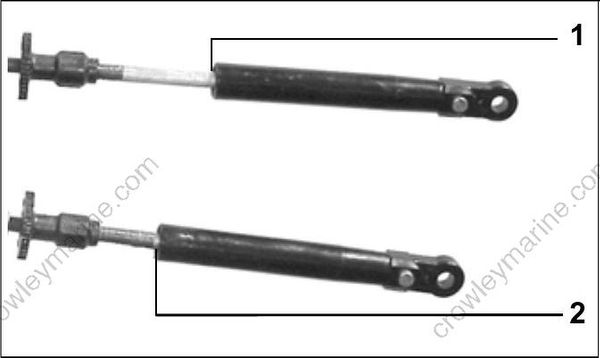
- Shift cable casing guide extended to midpoint DP0811
- Throttle cable casing guide retracted
Extend the control cables and lubricate them with Triple-Guard grease.
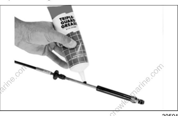
30501
Cable Retainer Clip Installation
When installing retainer clips on control arm linkage pins, clips should be locked and must not be bent or deformed.
For proper installation, review the following steps:
• Place washer on pin.
• Position retainer clip with straight section on the bottom and angled section on the top.
• Use long nose pliers to insert straight section of clip into linkage pin hole.
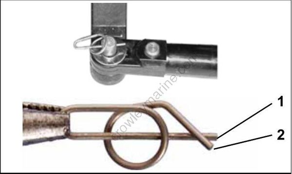
- Straight section DP0818
- Angled section DSC_4670
• Push the clip towards the hole while lifting on the curved end with the pliers.
• Be sure retainer clip fully engages the pin.
• Lock the retainer by moving the angled section behind the straight section.
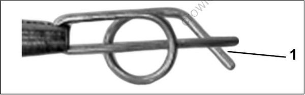
Locked Retainer Clip DP08
- Angled section behind straight section
Cable, Hose, and Wire Routing
To prevent accidental starting while servicing, disconnect the battery cables at the battery. Twist and remove all spark plug leads.
Refer to Control Cable Identification on p. 52. Remove cable entry grommet cover and grommet.
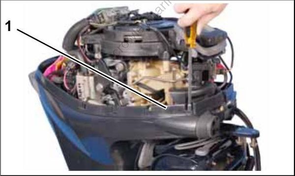
- Cable entry grommet cover 007120
Remove rubber membrane from grommet holes as needed. Install cables and wiring harness(es) through grommet as shown:
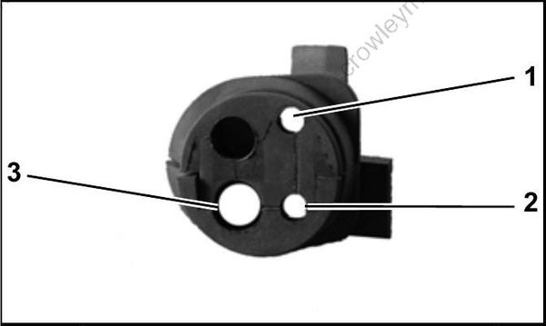
- Throttle cable 007129
- Shift cable
- Tiller wiring harness
When grommet is in place and all cables have been installed, tighten a tie strap around the outside of the grommet to form a watertight seal around the cables. Place blank sealing decal on lip of lower motor cover at each harness connector tie strap to prevent water intrusion.
- Tie strap 007127
- Blank sealing decal
After installation, make sure there is enough clearance for all cables to avoid binding or chafing through all engine steering and tilting angles.
Control Cable Installation
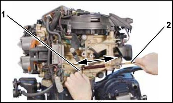
Refer to Control Cable Identification on p. 52. Make sure the remote control is in NEUTRAL, and throttle is in the IDLE position. Removal of lower motor covers is NOT required. Some images show lower covers removed for clear illustration. Place the shift cable on the shift lever pin. Hold the shift linkage in NEUTRAL. Push and pull on the shift cable and observe the cable slack. Hold the casing guide in the center of the slack.
Adjust the shift cable trunnion to align with the center of the trunnion block.
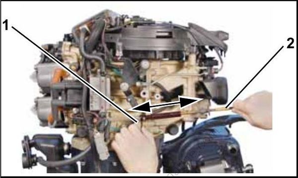
- Shift linkage 007215
- Shift cable
Install cable retainer and screw. Tighten screw to a torque of 60 to 84 in. lbs. (7 to 9.5 N·m).
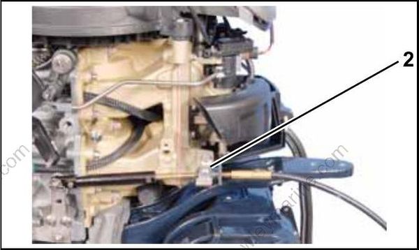
- Cable retainer 007121
With remote control lever in NEUTRAL, pull firmly on throttle cable casing to remove slack.
With engine throttle lever against stop, place the cable trunnion into the upper
anchor pocket and adjust the trunnion nut so the casing fits onto the throttle lever pin.
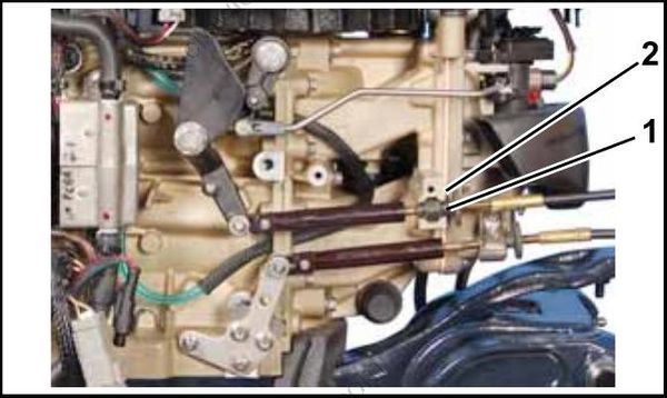
- Throttle cable trunnion 007217
- Trunnion block
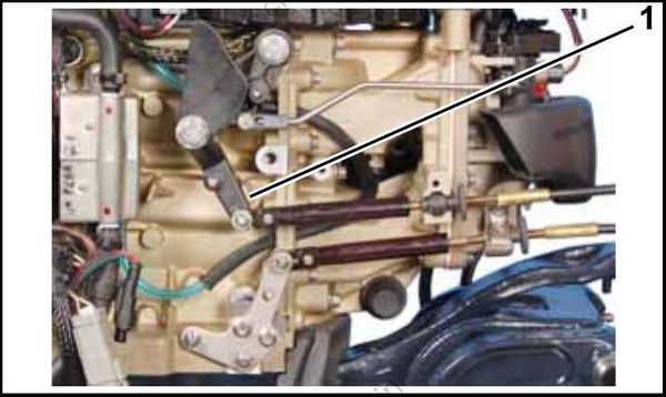
- Idle stop 007216
IMPORTANT: Move control handle to FOR WARD and pull back slowly to NEUTRAL. Make sure the engine throttle lever is against the stop. If not, remove slack by adjusting cable trunnion.
Install cable retainer and screw. Tighten screw to a torque of 60 to 84 in. lbs. (7 to 9.5 N·m).
Install washers and retainer clips on shift lever and throttle pins. Refer to Cable Retainer Clip Installation on p. 52.
System Check Harness Connections
Before installing electrical connectors, check that the seal is in place. Clean off any dirt from connectors. Apply a light coat of Electrical Grease to the seal only. DO NOT fill connectors with Electrical Grease.
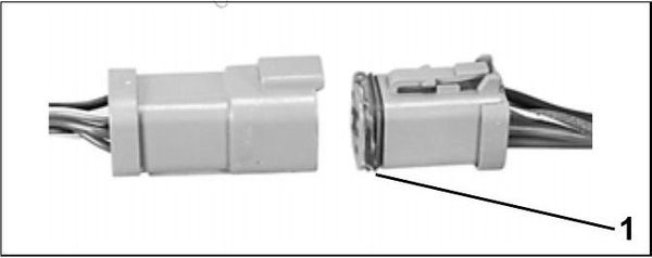
- Seal 42079A
Route electrical harness along the edge of the lower engine cover.
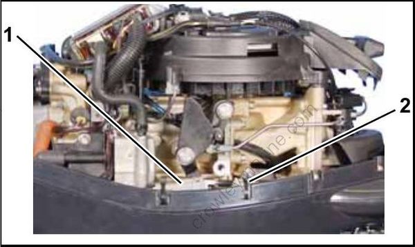
- Key switch connector 007263
- Tachometer connector
Secure connectors to lower motor cover with two tie straps as shown.
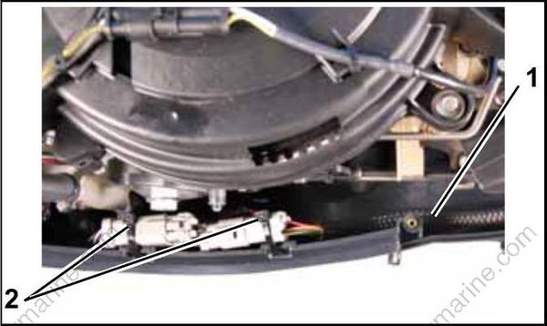
- Wire routing 007125
- Secure with two tie straps
Route trim and tilt connector under air silencer. Use tie strap to secure connector as shown.
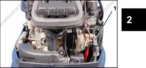
- Trim and tilt connector 007264
Install battery cables and secure with tie strap.
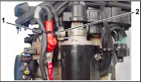
- Tie strap 007240
- Battery cable ground
Route battery cable through grommet of port lower motor cover.
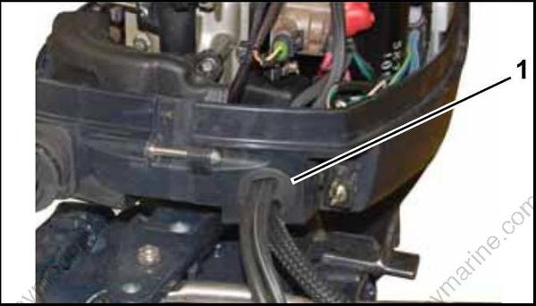
- Battery cable grommet 008009
BE SURE all harnesses and wires are not pinched, cannot contact flywheel, and do not interfere with moving throttle or shift linkages.
