Wire harness
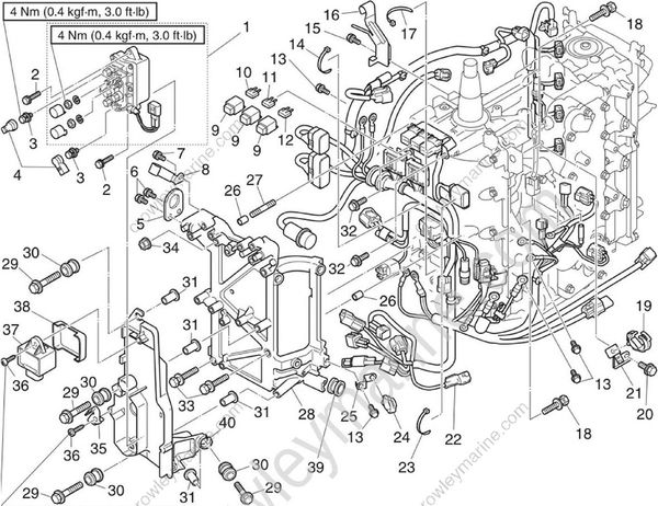
| No | Part name | Q’ty | Remarks |
|---|---|---|---|
| 1 | PTT relay | 1 | |
| 2 | Bolt | 2 | M6 x 20 mm |
| 3 | PTT motor lead bolt | 2 | M6 x 10 mm |
| 4 | Cap | 2 | |
| 5 | Engine hanger | 1 | |
| 6 | Bolt | 2 | M6 x 20 mm |
| 7 | Bolt | 1 | M6 x 14 mm |
| 8 | Holder | 1 | |
| 9 | Cap | 3 | |
| 10 | Fuse | 2 | 20 A, for battery, spare is included |
| 11 | Fuse | 2 | 20 A, for engine start switch and PTT switch, spare is included |
| 12 | Fuse | 2 | 20 A, for main relay, spare is included |
| 13 | Bolt | 4 | M6 x 20 mm |
| 14 | Plastic tie | 1 | |
| 15 | Bolt | 1 | M6 x 14 mm |
| 16 | Holder | 1 |
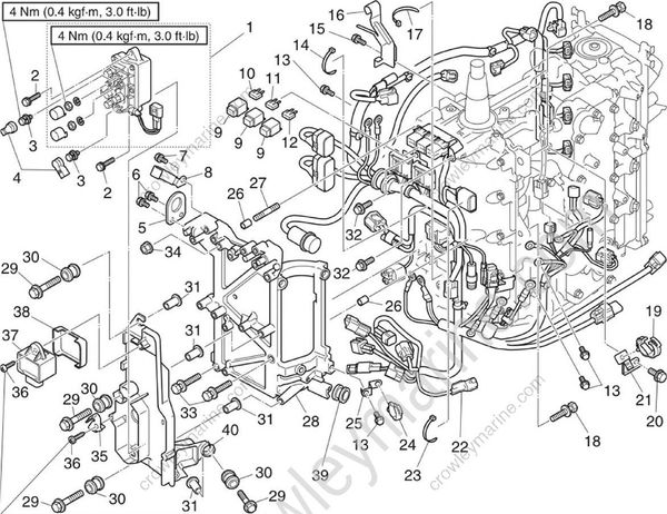
| No. | Part name | Q’ty | Remarks |
|---|---|---|---|
| 17 | Plastic tie | 1 | |
| 18 | Bolt | 2 | M8 x 25 mm |
| 19 | Holder | 1 | |
| 20 | Bolt | 1 | M6 x 14 mm |
| 21 | Bracket | 1 | |
| 22 | Wire harness | 1 | |
| 23 | Plastic tie | 1 | |
| 24 | Holder | 1 | |
| 25 | Bracket | 1 | |
| 26 | Dowel pin | 2 | |
| 27 | Stud bolt | 1 | M8 |
| 28 | Bracket | 1 | |
| 29 | Bolt | 4 | M6 x 28 mm |
| 30 | Grommet | 4 | |
| 31 | Collar | 4 | |
| 32 | Bolt | 2 | M6 x 14 mm |
| 33 | Bolt | 2 | M8 x 35 mm |
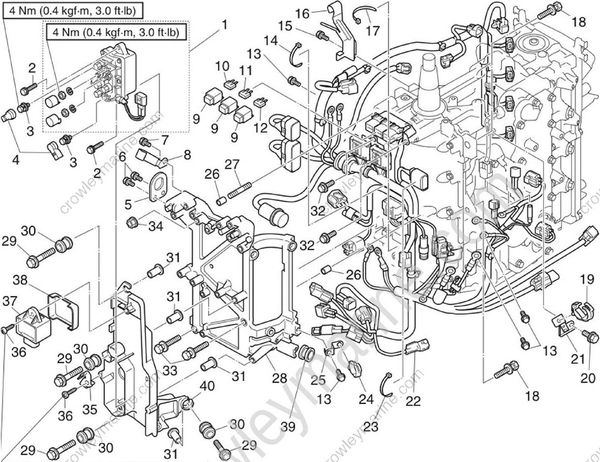
| No. | Part name | Q’ty | Remarks |
|---|---|---|---|
| 34 | Nut | 1 | M8 |
| 35 | Bracket | 1 | |
| 36 | Screw | 2 | M6 x 20 mm |
| 37 | Main relay | 1 | |
| 38 | Cover | 1 | |
| 39 | Grommet | 1 | |
| 40 | Bracket | 1 |
Removing the wire harness
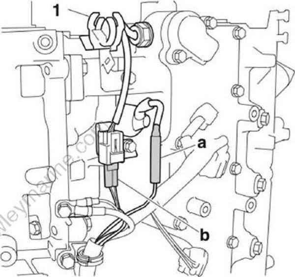
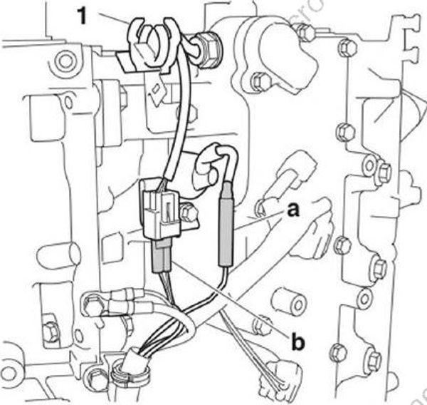
Disconnect the oil pressure switch connector “a” and thermo sensor coupler “b”.
Remove the bracket “1”.
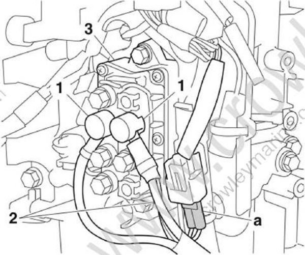
Remove the caps “1”, and then remove the PTT relay leads “2”.
Disconnect the PTT relay coupler “a”, and then remove the PTT relay “3”.
- Remove the bracket “1” along with the wire harness from the crankcase.
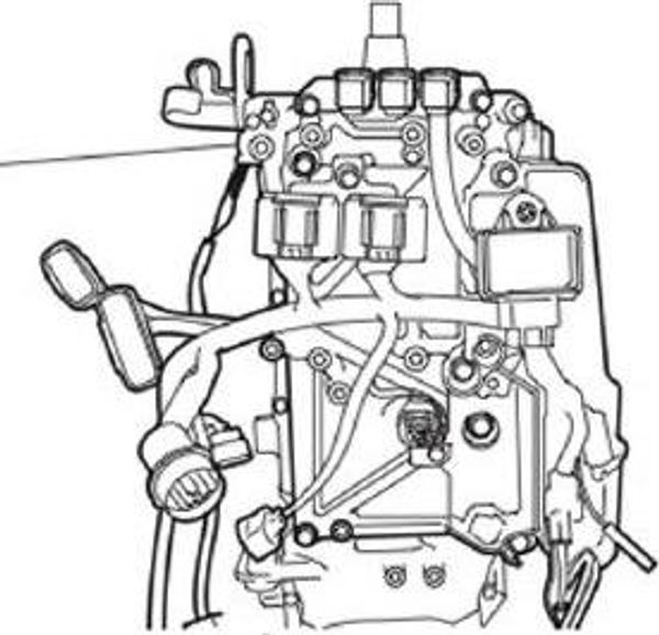
- Remove the main relay “1”, and then dis connect the main relay coupler “a”.

- Remove the ground leads “1” and “2”, and then remove the bracket “3”.
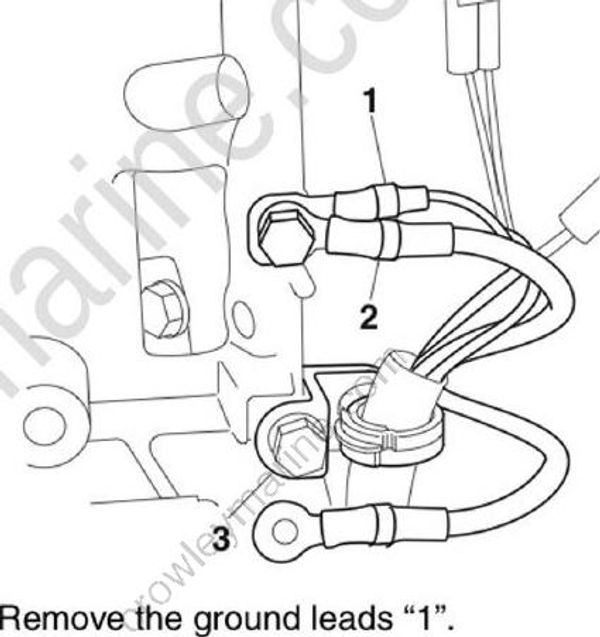
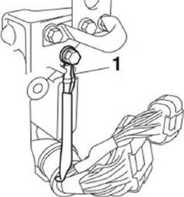
- Remove the ground leads "1".
- Remove the fuse holders “1”, joint connectors “a”, and YDIS coupler “b”.

- Remove the bracket “1” along with the wire harness.

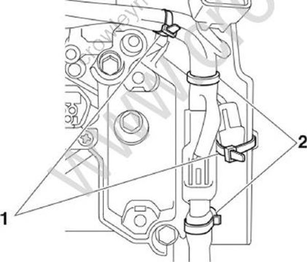
- Remove the plastic ties “1” and holders “2”.
Installing the wire harness
To install all the wire harnesses, See “Electrical component and wire harness routing” (5-1)
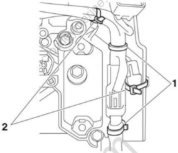
- Install the holder “1 ” and plastic tie “2”.
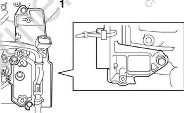
- Install the bracket “1” along with the wire harness.
Install the fuse holders “1”, joint connector “a”, and YDIS coupler “b”, and then tighten the YDIS coupler bracket screw “2” to the specified torque.
Install the harness clip “c”.
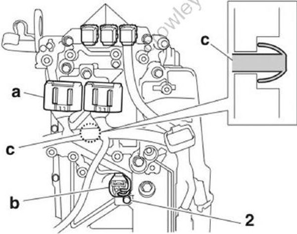
YDIS coupler bracket screw “2”: 2.5 N•m (0.25 kgf•m, 1.84 ft•lb)
- Install the ground leads “1” and “2”, and then install the bracket “3”.
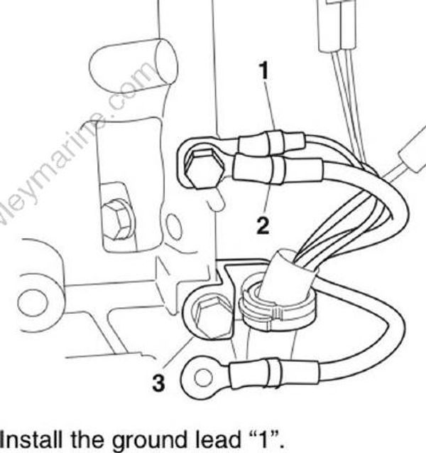
- Install the ground lead "1".

- Install the cover "1" to the main relay "2".
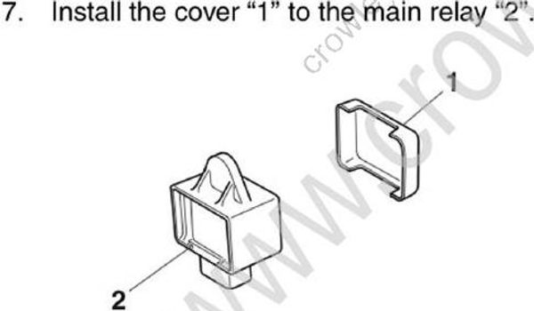
Connect the main relay coupler “a”.
Install the main relay “1”, and then tighten the main relay screw “2” to the specified torque.
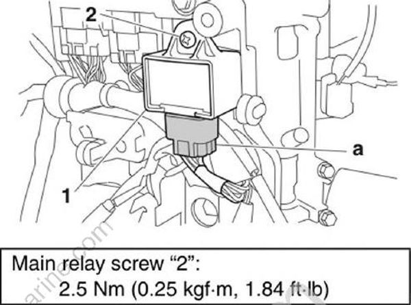
Main relay screw "2": 2.5 N•m (0.25 kgf•m, 1.84 ft•lb)
- Install the bracket “1” along with the wire harness to the crankcase.

Install the PTT relay “1”, and then connect the PTT relay coupler “a”.
Install the PTT relay leads “2”, and then tighten the PTT relay lead nuts “3” to the specified torque.
Install the caps "4".
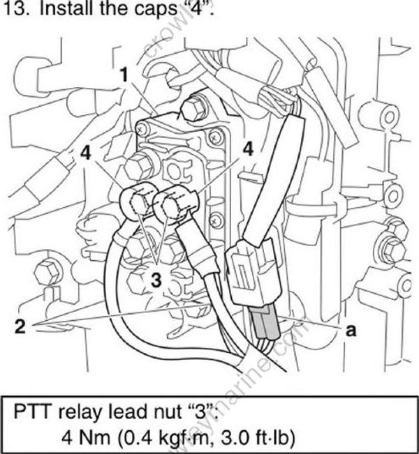
PTT relay lead nut "3": 4 Nm (0.4 kgf•m, 3.0 ft•lb)
Install the bracket “1”.
Connect the oil pressure switch connector “a”, thermo sensor coupler “b”.