

PREPARATION FOR REMOVAL
- Remove the top cowling.
- Remove the fuel tank and hose. Refer to the “FUEL SYSTEM” section in CHAPTER 4.
- Remove the carburetor.
Refer to the “FUEL SYSTEM” section in CHAPTER 4.
NOTE ON REMOVAL AND REASSEMBLY
Extent of removal: (1) Power unit removal
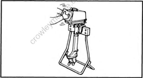
- Clean all dirt, mud, dust and foreign material from the engine before the engine is removed and disassembled.
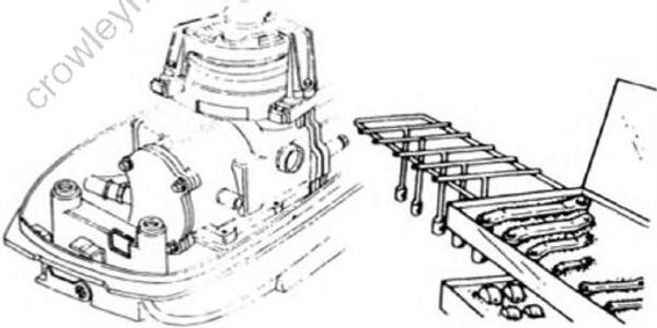
- To ensure that you can perform the work cleanly and efficiently, check that you have the proper tools and cleaning equipment before commencing engine removal and reassembly.
REMOVAL POINTS
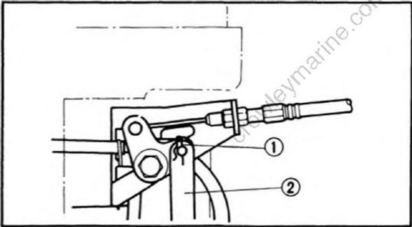
Start-in-gear protection wire (For start-in-gear protection model)
- Remove:
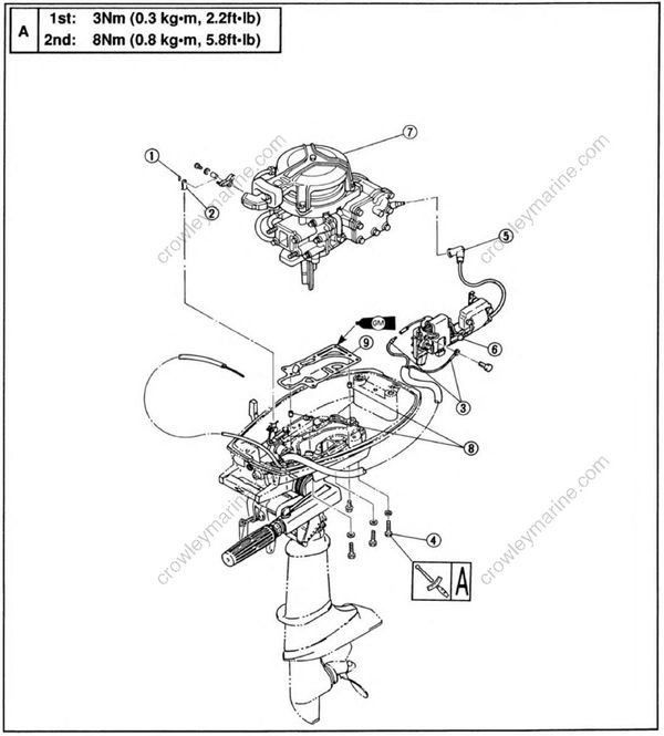
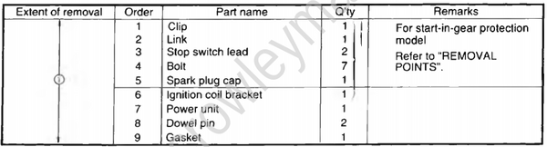
• Clip (1)
• Link (2)
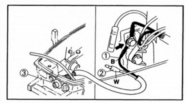
Stop switch/Engine stop switch lead
- Remove:
• Black (B) lead (1) (ground lead) - Disconnect:
• White (W) lead (2) - Remove:
• Stop switch (3)
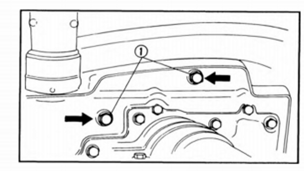
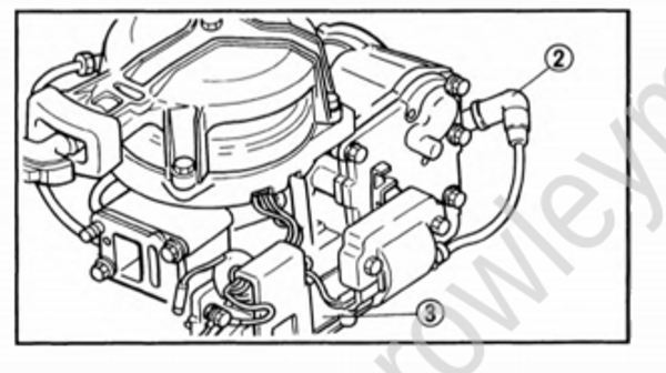
Ignition coil bracket
- Remove:
• Bolt (1)
• Spark plug cap (2)
• Ignition coil bracket (3)
ASSEMBLY AND INSTALLATION
Always use new gaskets, oil seals and O-rings. The use of any used oil seal or O-ring may result in oil leakage due to invisible scratches or stretches.
Apply grease to parts where specified.
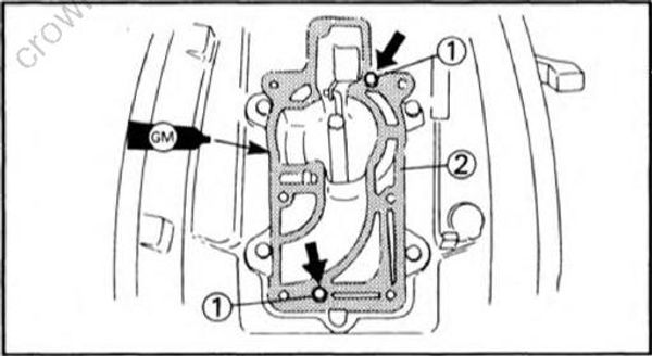
Power unit
- Apply:
• Gasket Maker
Onto both faces of the gasket.
Clean the contacting surfaces of crankcase and bottom cowling.
- Install:
• Dowel pin (1)
• Gasket (2) (new)
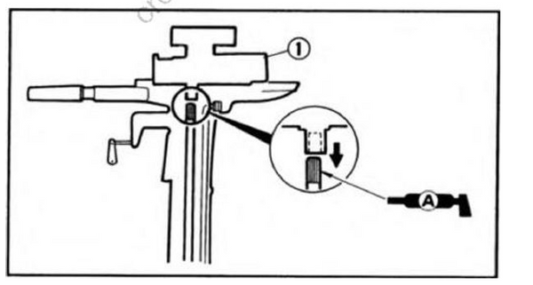
- Install:
• Power unit (1)
Insert the drive shaft into the crankshaft. If the splines will not come in complete mesh, rotate the crankshaft a little so that they are in mesh correctly.
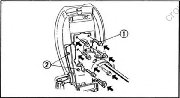
- Install:
• Mount bolt (1)
• Mount bolt (2)
Tighten the bolts in two steps of torque.
Mount bolt:
1st : 3 Nm (0.3 kg•m, 2.2 ft•lb)
2nd : 8 Nm (0.8 kg•m, 5.8 ft•lb)
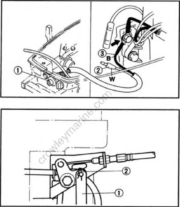
- Install:
• Stop switch/Engine stop switch (1)
• White lead (2)
• Black lead (3)
- Install:
• Link (1)
• Clip (2)
- Adjust:
• Throttle wire
Refer to the “PERIODIC SERVICE" section in CHAPTER 3.
- Adjust:
• Idle speed
Refer to the “PERIODIC SERVICE” section in CHAPTER 3.
