

Power unit assembly
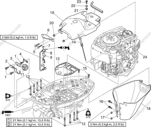
| No. | Part name | Q’ty | Remarks |
|---|---|---|---|
| 1 | Bolt | 3 | M6 x 20 mm |
| 2 | Grommet holder | 1 | |
| 3 | Grommet | 1 | |
| 4 | Cable guide | 1 | |
| 5 | Bolt | 2 | M6 x 22 mm |
| 6 | Bracket | 1 | |
| 7 | Collar | 1 | |
| 8 | Shift position switch | 1 | |
| 9 | Plate | 1 | |
| 10 | Screw | 2 | M4 x 16 mm |
| 11 | Rigging grommet | 1 | |
| 12 | Power unit mounting bolt | 8 | M8 x 80 mm |
| 13 | Gasket | 1 | Not reusable |
| 14 | Dipstick | 1 | |
| 15 | Bolt | 2 | M6 x 16 mm |
| 16 | Screw | 2 | M6 x 25 mm |
| 17 | Nut | 2 | M6 |
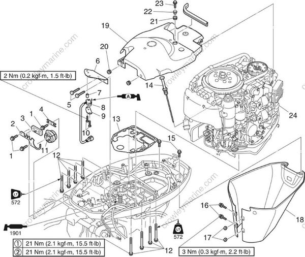
| No. | Part name | Q’ty | Remarks |
|---|---|---|---|
| 18 | Apron | 1 | |
| 19 | Cover | 1 | |
| 20 | Grommet | 2 | |
| 21 | Grommet | 1 | |
| 22 | Collar | 1 | |
| 23 | Bolt | 1 | M6 x 20 mm |
| 24 | Power unit | 1 |
Removing the power unit
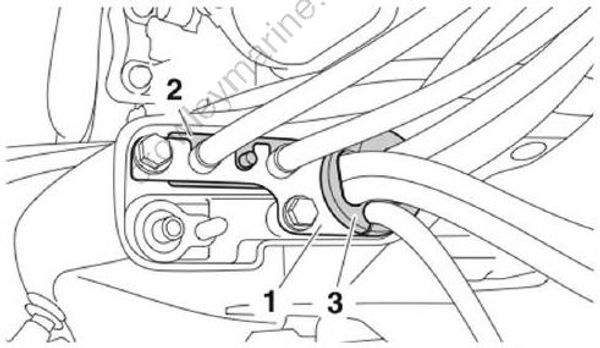
- Remove the grommet holder “1”, grommet “2”, and rigging grommet “3”.
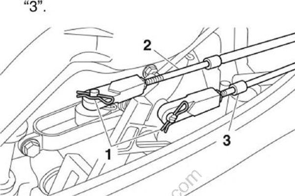
- Remove the clips “1”, and then disconnect the shift cable “2” and throttle cable "3".
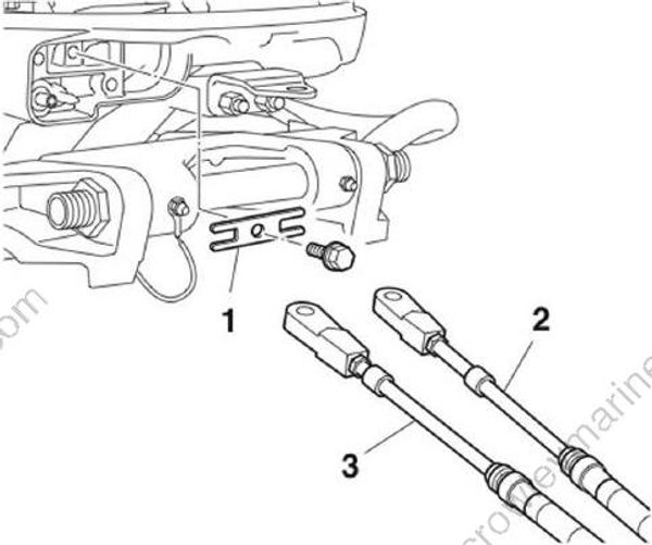
- Remove the cable guide “1”, shift cable “2”, and throttle cable “3”.
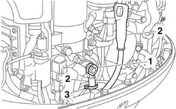
- Remove the cover “1”, battery cables “2”, and plastic tie “3”.
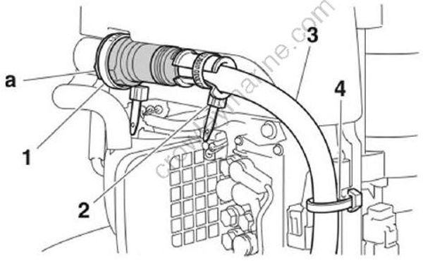
Remove the plastic ties “1” and “2”, and then disconnect the main wire harness coupler “a”.
Remove the main wire harness “3” from the plastic tie “4”.
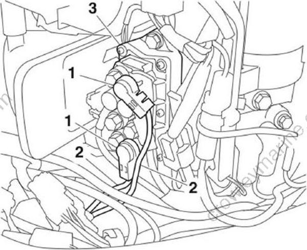
- Remove the caps “1”, and then remove the PTT motor leads “2” from the PTT relay “3”.
Remove the Command Link Multifunction Gauge harness coupler “a”.
Disconnect the Command Link Multifunction Gauge harness coupler “a” or Gauge harness coupler “b”.
Disconnect the neutral switch coupler “c” and PTT switch coupler “d”.
Remove each harness from the clamps "1".
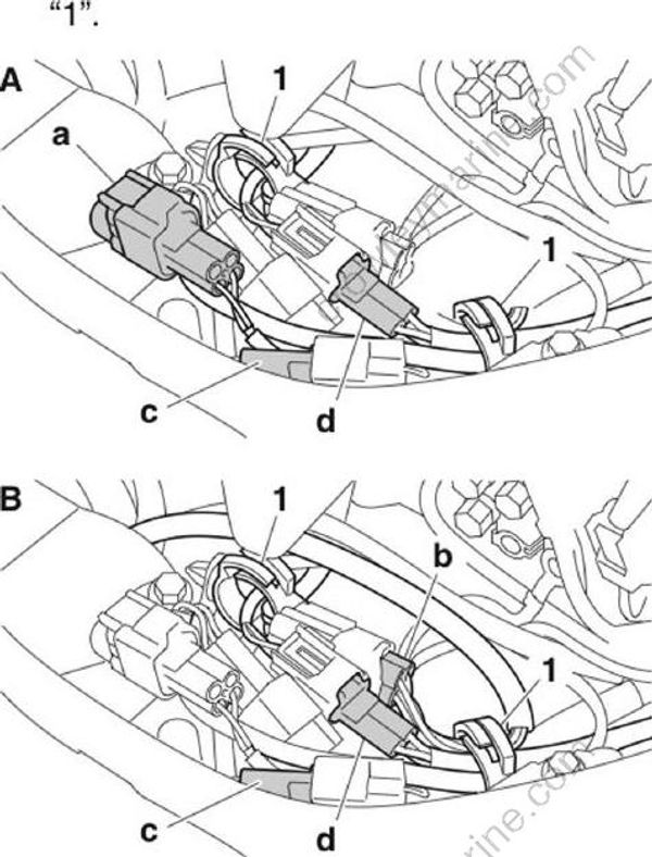
A. Command Link Multifunction Gauge
B. Conventional gauge
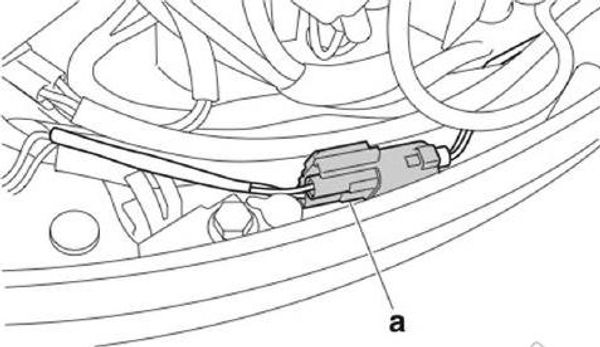
- Disconnect the trim sensor coupler “a”.
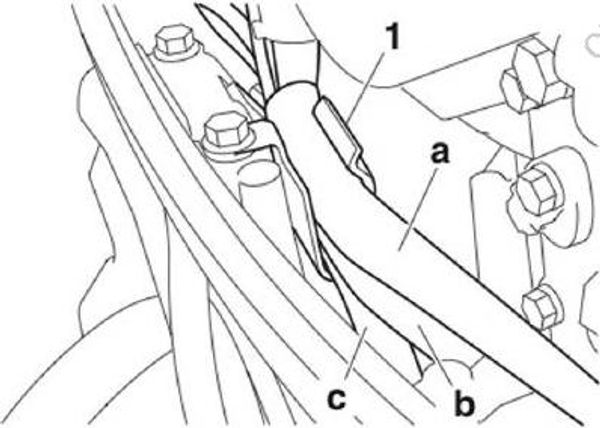
- Remove the stator assembly harness “a”, water pressure sensor harness “b”, and speedometer hose “c” from the holder “1”.
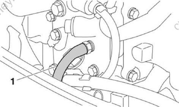
- Disconnect the cooling water hose “1”.
- Disconnect the fuel hose “1” from the filter assembly “2”.
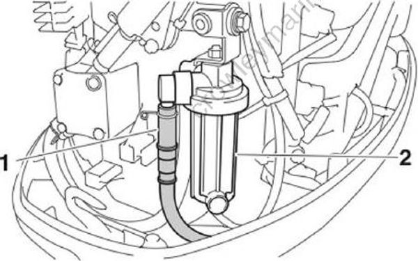
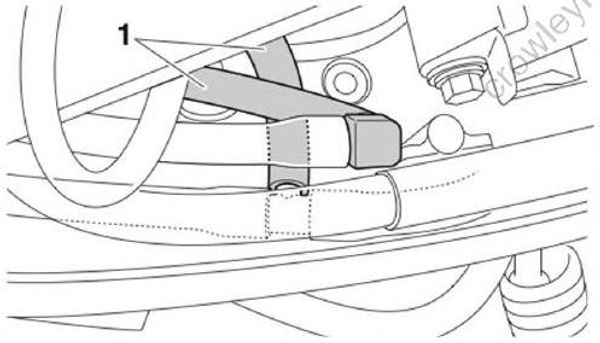
- Disconnect the cooling water hoses “1”.
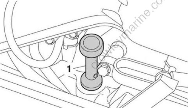
- Remove the dipstick “1”.
- Remove the clip “1”, and then remove the shift rod lever “2”.
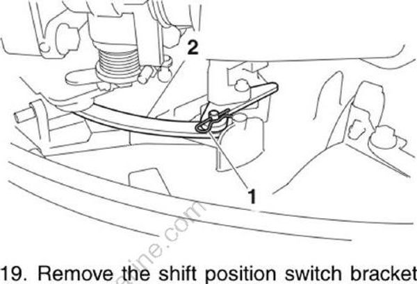
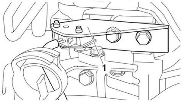
- Remove the shift position switch bracket “1”.
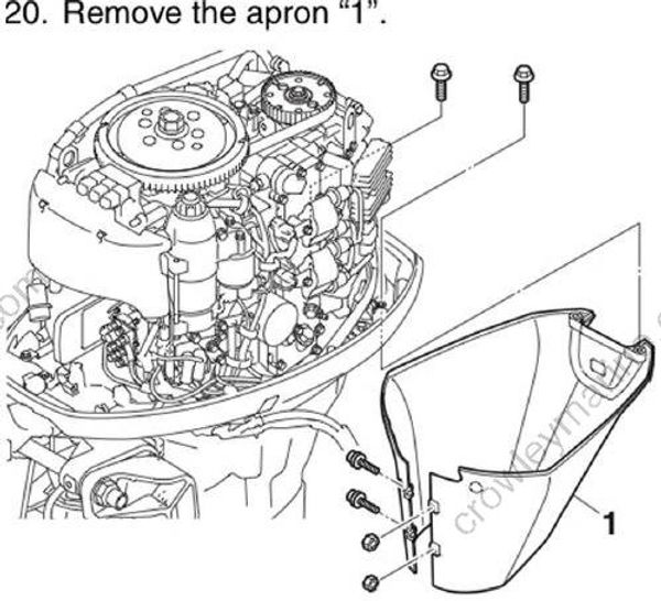
- Remove the apron "1".
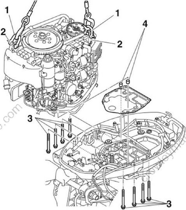
Install the shackles “1” to the engine hangers “2”, and then install the lifting harnesses to the shackles “1”.
Suspend the power unit.
Remove the power unit mounting bolts “3”, and then remove the power unit and dowel pins “4”.
Installing the power unit
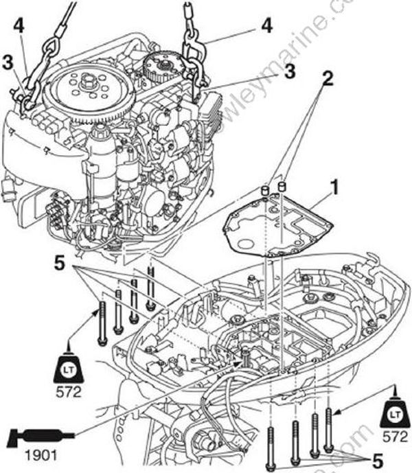
Clean the power unit mating surface, and then install a new gasket “1” and dowel pins “2”.
Install the shackles “3” to the engine hangers “4”, and then install the lifting harnesses to the shackles “3”.
Install the power unit using the power unit mounting bolts “5”.
Tighten the power unit mounting bolts “1” and oil pan bolts “2”, and “3” to the specified torque in the order [1], [2], and so on.
Tighten the power unit mounting bolts “1” to the specified torque, and then tighten them once again.
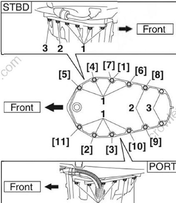
Power unit mounting bolt “1”:
1st: 21 Nm (2.1 kgf⋅m, 15.5 ft⋅lb)
2nd: 21 Nm (2.1 kgf⋅m, 15.5 ft⋅lb)
Oil pan bolt “2” and “3”: 21 Nm (2.1 kgf⋅m, 15.5 ft⋅lb)
- Install the apron “1” and apron bolts “2”, and then tighten the apron screws “3” to the specified torque.
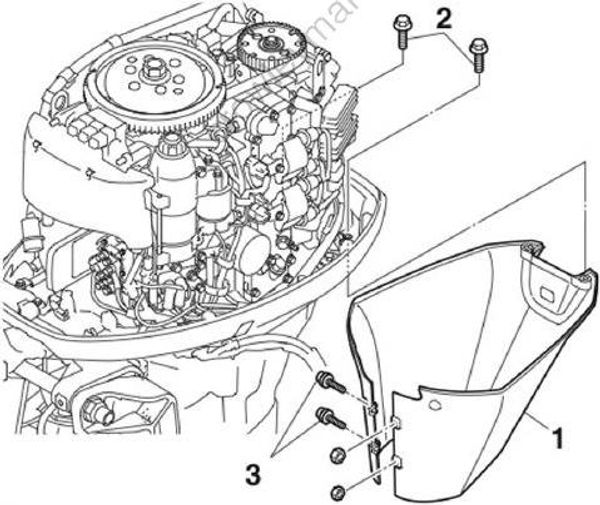
Apron screw “3”: 3 Nm (0.3 kgf⋅m, 2.2 ft⋅lb)
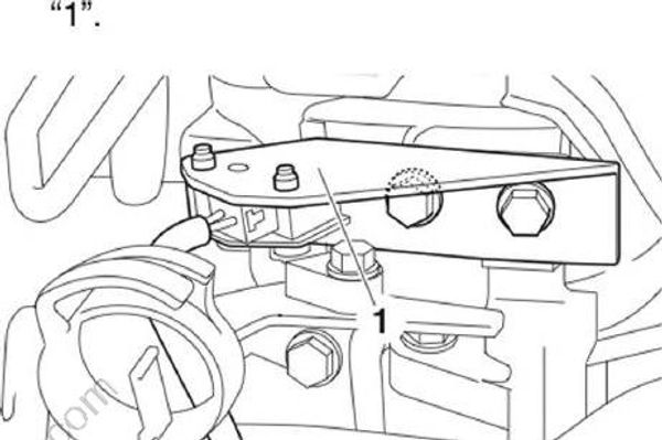
- Install the shift position switch bracket "1".
- Install the shift rod lever “1”, and then install the clip “2”.
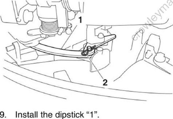
- Install the dipstick "1".
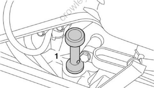
- Connect the cooling water hose “1” that is connected to the exhaust cover with the cooling water hose “2” that is connected to the exhaust guide.
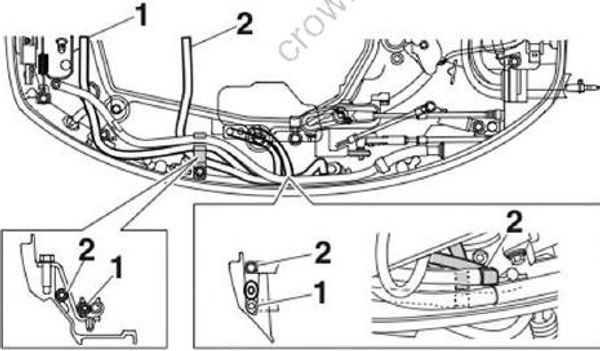
- Connect the fuel hose “1” to the fuel filter assembly “2”, and then fasten the fuel hose “1” using the clamp “3”.
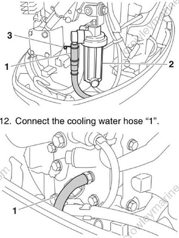
Connect the cooling water hose "1".
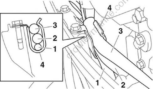
Install the speedometer hose “1”, water pressure sensor harness “2”, and stator assembly harness “3” to the holder “4”.
- Connect the trim sensor coupler “a”.
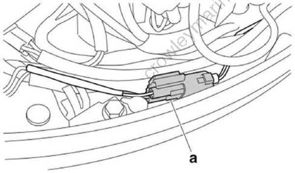
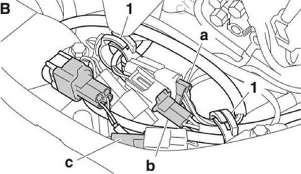
Connect the gauge harness coupler “a” and PTT switch coupler “b”.
Connect the shift position switch coupler “c” and Command Link Multifunction Gauge harness coupler “d”.
Install each harness to the clamps “1”. See “Bottom cowling” (5-9).
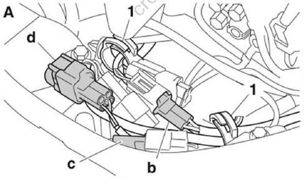
A. Command Link Multifunction Gauge
B. Conventional gauge
Install the PTT motor leads “1” to the PTT relay “2”, and then tighten the PTT motor lead bolts “3” to the specified torque.
Install the caps “4”.
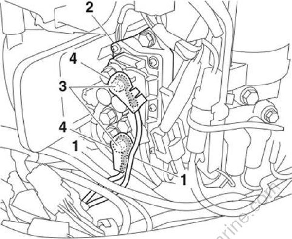
PTT motor lead bolt “3”: 3.5 Nm (0.35 kgf⋅m, 2.6 ft⋅lb)
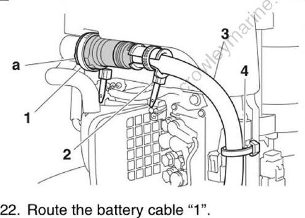
Connect the main harness coupler “a”, and then fasten it to the cover using the plastic ties “1” and “2”.
Fasten the main wire harness “3” to the bracket using the plastic tie “4”.
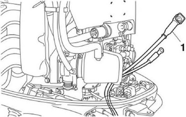
- Route the battery cable "1".
• Route the battery cable “1” to the outside of all wire harnesses.
• The positive battery cable is marked with red tape.
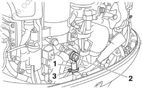
Install the negative battery cable “1”, and then install its cover “2”.
Fasten all wire harnesses to the negative battery cable “a” using the plastic tie “3”.
Bind the wire harnesses so that they do not interfere with the oil filter.
Connect the positive battery cable “a” and install the washer “2”, and then tighten the positive battery cable nut “3” to the specified torque.
Install the rubber cap “b”.
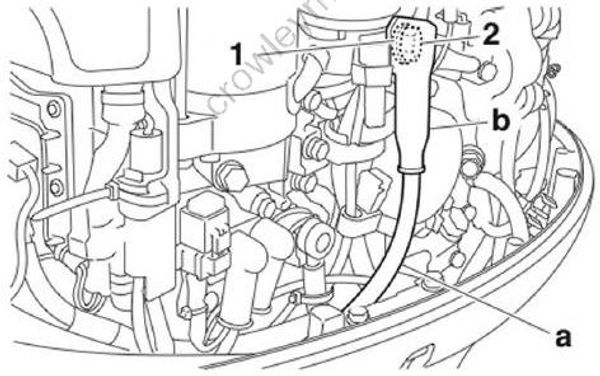
Positive battery cable nut “3”: 9 Nm (0.9 kgf⋅m, 6.6 ft⋅lb)
- Install the shift cable and throttle cable. See “Installing the shift cable and throttle cable” (3-12).
