Hull Centerline
Use the chines of the boat as reference points to locate the centerline of the boat transom.
Use a straightedge to draw a line connecting the port and starboard chines.
Use a framing square to accurately place a vertical line on the transom. The centerline of the hull should be in line with the keel, and perpendicular to the midpoint of the line connecting the chines.
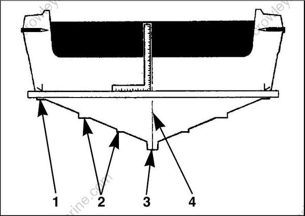
- Chine
- Strake
- Keel
- Hull centerline
Dual-Outboard Centerlines
The following table lists standard ABYC centerline spacing between outboards in dual installations:
| 2 and 3 cylinder | 22 in. (559 mm) |
|---|---|
| V4 and V6 | 26 in. (660 mm) |
Some applications may require changes in this dimension to avoid strakes, to adjust for transom height, or for performance reasons. Best performance can be determined only through testing. Refer to boat manufacturer for recommendations.
If the standard spacing does not allow full steering travel in a particular installation, it may be necessary to increase the spacing.
IMPORTANT: Some steering systems may require additional spacing. Refer to steering system manufacturer for recommendations.
The top edge of the transom should be more than twice the width of the dual-outboard centerline spacing dimension. Bracket installations may not require this consideration.
Measure the transom for dual-outboard spacing after the centerline of the hull is established.
Divide the spacing dimension by two. Use the resulting number to space the outboard center lines from the hull centerline.
EXAMPLE: A 26 in. (660 mm) dual-outboard spacing would result in two outboard centerlines, each 13 in. (330 mm) from the hull centerline.
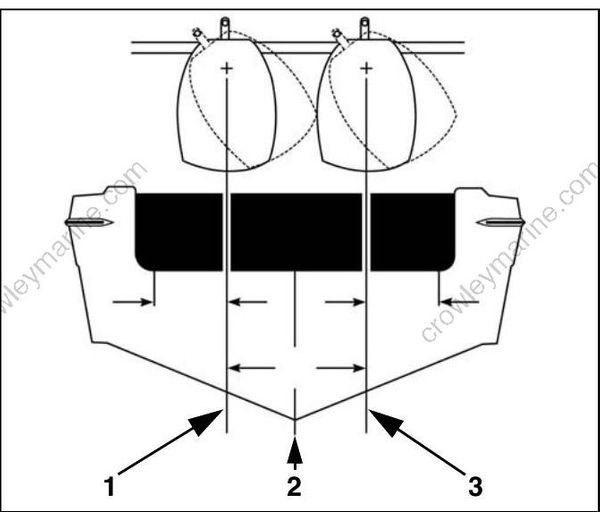
- Port centerline
- Hull centerline
- Starboard centerline
Transom Height
Make sure the transom height matches the length of the outboard to be installed.
- A 19 to 21 in. (48.3 to 53.3 mm) transom height uses a 20 in. (50.8 mm) shaft outboard.
- The shaft length of the outboard being installed should come close to matching the transom height of the boat.
- Refer to SPECIFICATIONS in outboard Operator’s Guide for transom height.
Determine transom height by measuring from the top edge of the transom, along the centerline.
For dual-outboard installations, transom height should be measured at the outboard centerlines.
Use a straightedge as a reference to extend the bottom of the boat.
Position the straightedge along centerline. The distance from the top edge of the straightedge to the top edge of the transom is the actual transom height.
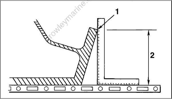
- Top edge of transom
- Actual transom height
15–30 HP MODELS
With the outboard installed on the boat:
• Generally the anti-ventilation plate of the gearcase should align with the bottom of the hull.
• The anti-ventilation plate should NOT extend more than 2 in. (5 cm) BELOW the bottom of the hull.
Transom Drilling Locations
75–300 HP, ALL MODELS
40–60 HP, POWER TRIM MODELS
25–30 HP, POWER TRIM MODELS
All models use the standard ABYC 4-Bolt mounting pattern.
Use Transom drill fixture, P/N 434367 or P/N 385368, as a guide for correct hole placement. If drill fixture is unavailable, refer to Drilling and Hardware Diagrams on p. 36 for measurements.
Position drill fixture on top of transom or bracket and align indicator points with centerline.
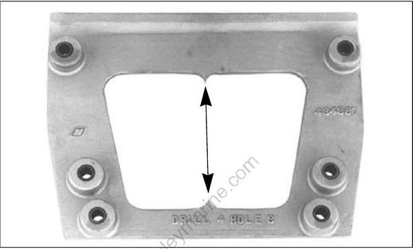
Transom drill fixture P/N 434367 (heavy duty)
The indicators are affected by the squareness of the top edge of the transom. If either side of the fixture must be raised more than ¼ in. (6 mm) above the transom's top surface to make both indicators align, the transom must be modified.
IMPORTANT: DO NOT assume that the top edge of the transom is straight. Position the drill fixture based on measurements aligning it to the bottom of the hull.
Maintain at least 1.75 in. (45 mm) of transom surface above the top mounting bolts.
Before drilling any mounting holes:
• Make sure the hole locations provide enough clearance for mounting bolts and washers.
• Check the inside area of the transom for obstructions.
• Check transom height(s) at centerlines.
Drill four ½ in. (13 mm) mounting holes in the appropriate locations.
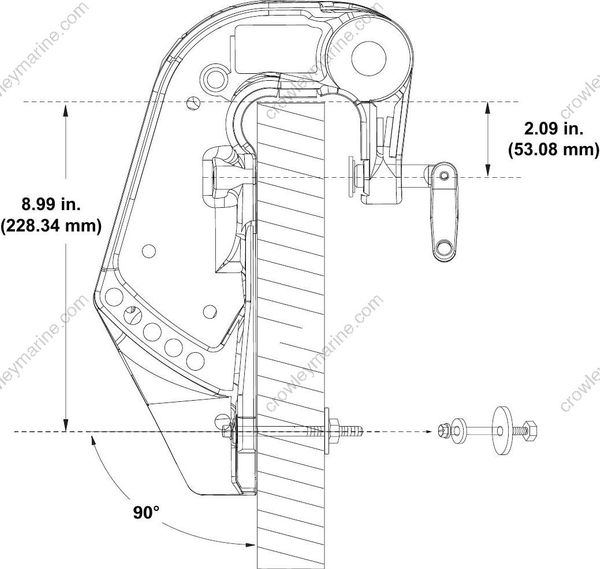
IMPORTANT: Be sure to drill the required holes perpendicular to transom surface.
40–65 HP, MANUAL TILT MODELS
25–30 HP, MANUAL TILT MODELS
15 HP, POWER TILT MODELS
Center the outboard on the transom (or mounting bracket) and tighten clamp screws by hand.
Use each stern bracket’s mounting holes as a guide to drill holes through the transom.
• 40–65 HP models require four 5/16 in. (8 mm) holes
• 25–30 HP models require two 5/16 in. (8 mm) holes
• 15 HP models require four 5/16 in. (8 mm) holes.
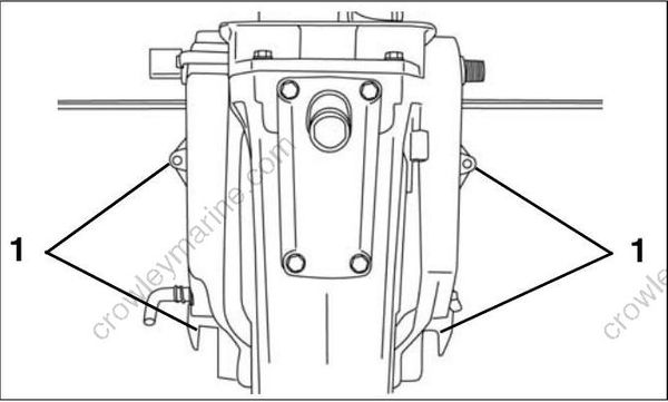
40 – 65 HP Models
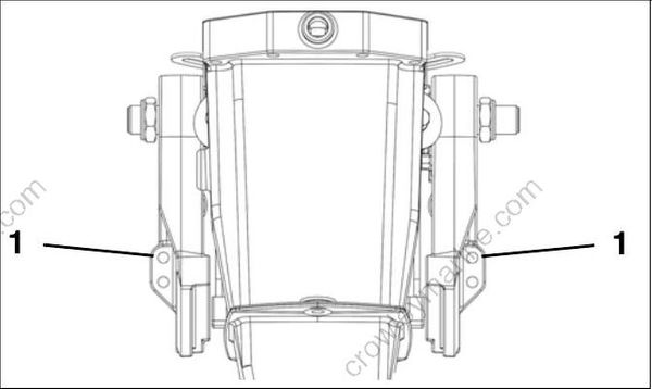
25 – 30 HP Models
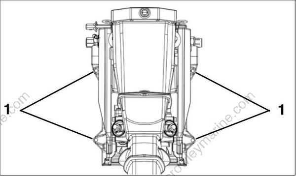
15 HP Models
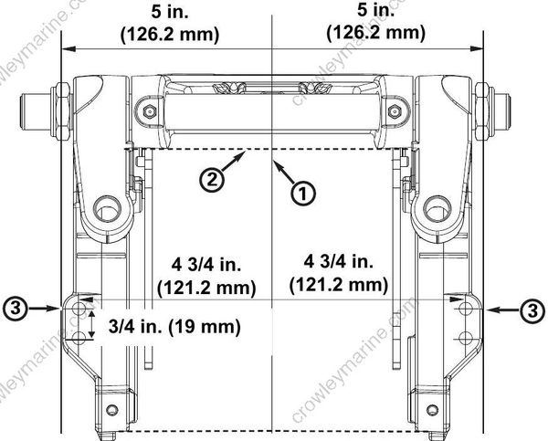
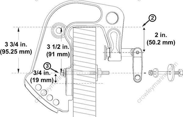
Drilling and Hardware Diagrams
75–300 HP, ALL MODELS; 40–60 HP, POWER TRIM MODELS; 25–30 HP, POWER TRIM MODELS
IMPORTANT: This is not a template.
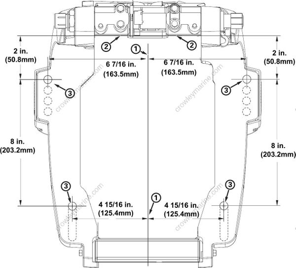
- Center of Transom
- Top of Transom
- 1/2” Bolt Hole Locations
- Outside of Transom
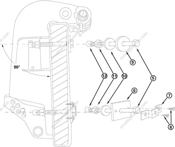
- Bolt *
- 318272 Plate
- 318273 Retainer
- 319886 Screw
- 307238 Washer
- 320248 Washer
- 313623 Nut
- 318572 Cap
Quantity
4
2
2
4
2
4
4
4
*Choose from the following bolt sizes:
327053 3 in. (76 mm)
318573 3 1/2 in. (89 mm)
336676 4 1/2 in. (114 mm)
331578 5 in. (127 mm)
354101 6 in. (152 mm)
354102 7 in. (178 mm)
354103 8 in. (203 mm)
354104 9 in. (229 mm)
IMPORTANT: This is not a template.
40–65 HP, MANUAL TILT MODELS
IMPORTANT: This is not a template.
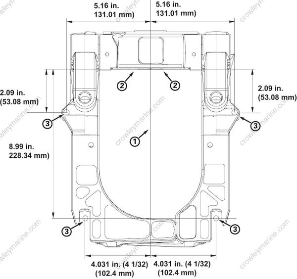
- Center of Transom
- Top of Transom
- 5/16” Bolt Hole Locations
IMPORTANT: This is not a template
25–30 HP, MANUAL TILT MODELS
IMPORTANT: This is not a template
- Center of Transom
- Top of Transom
- 5/16” Bolt Hole Locations
IMPORTANT: This is not a template..
15 HP, POWER TILT MODELS
IMPORTANT: This is not a template.
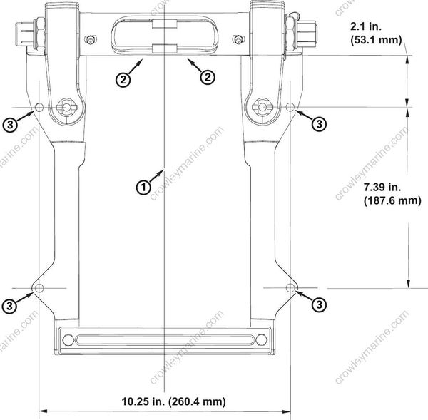
- Center of Transom
- Top of Transom
- 5/16” Bolt Hole Locations
IMPORTANT: This is not a template.