

OUTBOARD MOUNTING
IMPORTANT: Some rigging components, such as steering cables, must be fitted to the outboardbefore the outboard is mounted to the transom. Determine what equipment will be installed before mounting.
Mounting Height
Boat performance depends on outboard mounting height.
Generally, the anti-ventilation plate of the gearcase should align with the bottom of the hull. Conventional V-hulls often perform well with the antiventilation plate approximately 1 in. (25 cm) above the bottom of the hull.
Boats that exceed 50 MPH may benefit from higher outboard heights. Consult the boat manufacturer for specific outboard mounting height information for a particular hull.
Test outboard and boat performance at different heights until the best performance is achieved.
Be sure that outboard water pressure is not adversely affected by the mounting height of the outboard.
Mounting Bolt Installation
IMPORTANT: Use a marine sealant rated for above or below waterline use. RTV silicone is not approved for below waterline use. Polyurethane sealants are not easily removed and may damage outboard or boat mounting surfaces.
Apply marine sealer under hex heads of bolts, on the mounting plates, and to the bolt shanks.
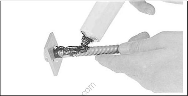
0078A
75–300 HP, ALL MODELS
40–60 HP, POWER TRIM MODELS
25–30 HP, POWER TRIM MODELS
Assemble transom mounting plates on mounting bolts.
Install the mounting bolts through the transom from the inside of the boat.
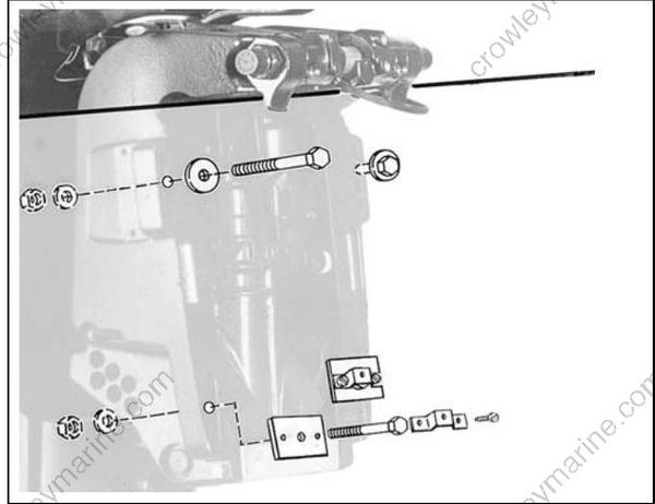
DR5536
Position the square aluminum transom mounting plates (when applicable) so the retainer holes are horizontal.
Position hex head of bolt with flats toward holes in the mounting plates. Install retainer over hex head of the bolt and secure it with screws provided.
Install all washers and nuts. Tighten nuts and bolts to a torque of 40 ft. lbs. (54 N·m).
If either side of the transom deforms or cracks when the bolts are tightened to their recommended torque, the transom construction may not be adequate or may be deteriorated. Structural failure of the transom could result in loss of boat control and injury to the occupants.
40–65 HP, MANUAL TILT MODELS
Manual tilt models require Transom Mounting Kit, P/N 394219. The kit includes a transom mounting plate and hardware for fastening outboard to transom.
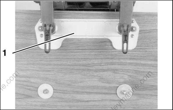
18961
- Transom mounting plate
The kit also includes clamp pads, P/N 315774, which must be used to secure mounting bolts in slots at the bottom of the outboard stern brackets.
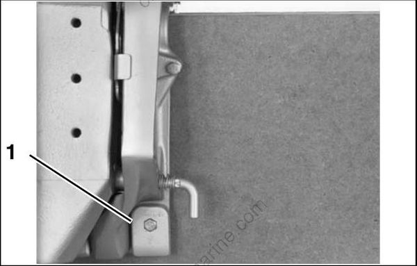
COB2505
- Clamp pad
Install the mounting bolts through the stern brackets and transom. Install round backing plates and locknuts onto bolts and tighten securely.
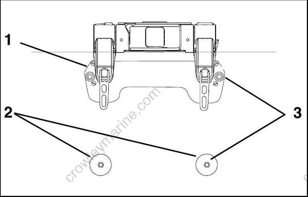
008015
- Transom mounting plate
- Round backing plates
- Locknuts
25–30 HP, MANUAL TILT MODELS
15 HP, POWER TILT MODELS
Install the mounting bolts through the stern brackets and transom. Install round backing plates and locknuts onto bolts and tighten securely.
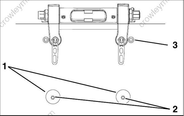
008014
- Round backing plates
- Locknuts
- Nut and washer (15 HP)
