

Ignition unit and component
OL: Indicates overload
- Connect the lighting coil coupler.
Checking the ignition spark
Disconnect the spark plug wire from the spark plug.
Connect the spark plug wire to the special service tool “1”.
Check the ignition spark using the YDIS “Stationary test”.
WARNING
Do not touch any of the connections of the special service tool.
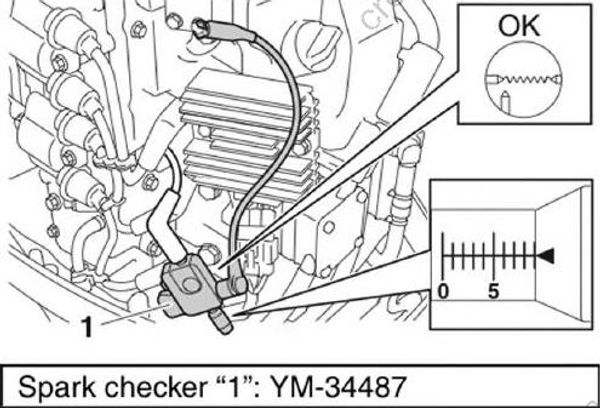
Spark checker "1": YM-34487
- Remove the special service tool, and then connect the spark plug wire.
Checking the spark plug wire
Remove the spark plug wires.
Measure the spark plug wire resistance.
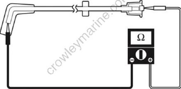
Spark plug wire resistance: 1.9-5.0 kQ at 20 °C (68 °F)
- Install the spark plug wires.
Checking the ignition coil
Disconnect the ignition coil couplers “a” and “b”.
Turn the engine start switch to ON, and then measure the input voltage at the ignition coil coupler terminal and ground.
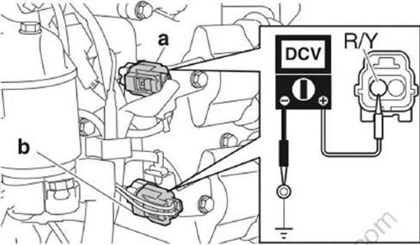
Ignition coil input voltage: Red/Yellow (R/Y)-Ground 12 V (battery voltage)
Turn the engine start switch to OFF.
Disconnect the spark plug wires from the ignition coils.
Measure the ignition coil resistance.
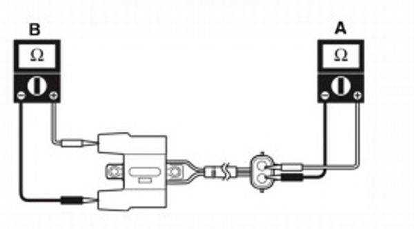
Ignition coil resistance:
Primary coil “A”: 1.530-2.070 Q @ 20 °C (68 °F)
Secondary coil “B”: 12.50-16.91 kQ @ 20 °C (68 °F)
- Connect the spark plug wires and ignition coil couplers .
Checking the pulser coil
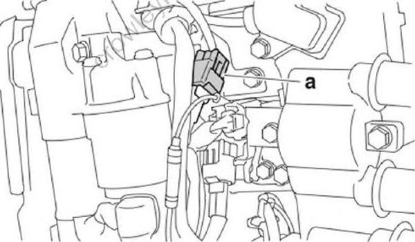
- Disconnect the pulser coil coupler “a”.
Connect the special service tool “1”.
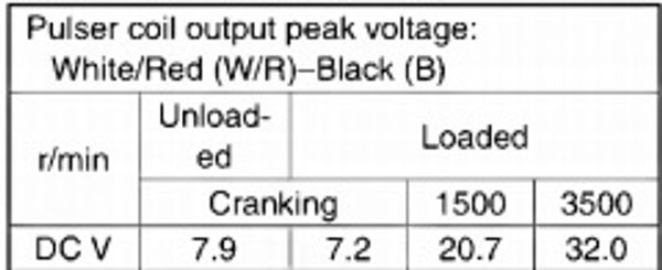
Measure the pulser coil output peak volt age.
TIP:
When measuring the pulser coil output peak voltage under the cranking (unloaded) condition, disconnect the coupler “a” to pre vent the engine from starting.
When measuring the pulser coil output peak voltage under the cranking (loaded) condition, remove the clip from the engine shut-off switch to prevent the engine from starting.
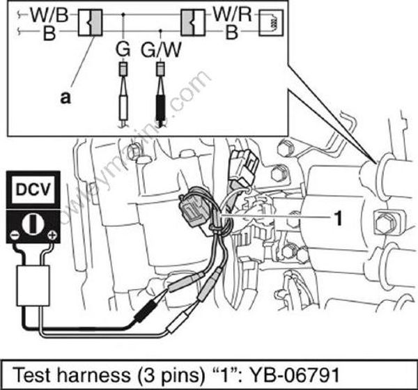
Test harness (3 pins)"1": YB-06791
- Disconnect the special service tool, and then measure the pulser coil resistance.
Pulser coil resistance:
White/Red (W/R)-Black (B)
396.0-594.0 Q @ 20 °C (68 °F)
- Connect the pulser coil coupler.
Checking the intake air temperature sensor
The intake air pressure sensor is a compo nent of the intake air pressure/temperature sensor.
Measure the ambient temperature.
Connect the YDIS to display “Intake air temperature”.
Check that the difference between the ambient temperature and the displayed intake temperature is within ± 5 °C (±9 °F).
TIP:
- Check the intake air temperature sensor when the engine is cold.
- When checking the intake air temperature sensor, remove the top cowling and do not start the engine.
Checking the intake air pressure sensor
The intake air pressure sensor is a component of the intake air pressure/temperature sensor.
Disconnect the intake air pressure/temperature sensor coupler “a”.
Turn the engine start switch to ON, and then measure the input voltage at the intake air pressure sensor coupler.
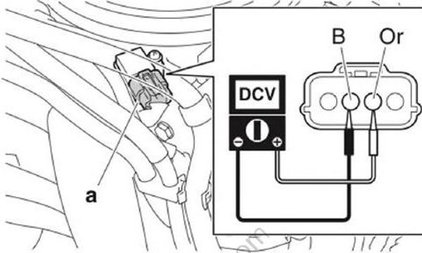
Intake air pressure/temperature sensor voltage: Orange (Or)-Black (B) 4.75-5.25 V
Turn the engine start switch to OFF.
Connect the intake air pressure/temperature sensor coupler.
Checking the thermo sensor
Disconnect the thermo sensor coupler “a”.
Turn the engine start switch to ON, and then measure the input voltage at the thermo sensor coupler.
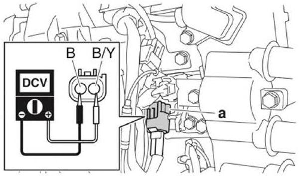
Thermo sensor input voltage: Black/Yellow (B/Y)-Black (B) 4.75-5.25 V
Turn the engine start switch to OFF.
Remove the thermo sensor.
Place the thermo sensor in a container of water and heat the water slowly.
Measure the thermo sensor resistance.
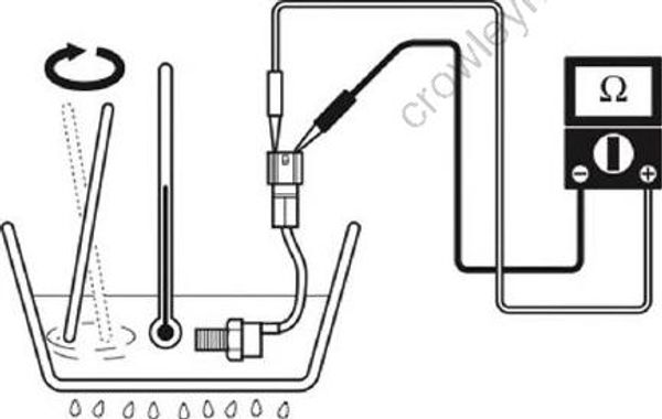
Thermo sensor resistance (reference data):
2.493 kΩ @ 20 °C (68 °F)
0.589 kΩ @ 60 °C (167 °F)
0.193 kΩ @ 100 °C (212 °F)
Install the thermo sensor. See “Cylinder block”
Connect the thermo sensor coupler.
Checking the shift position switch
Disconnect the shift position switch coupler “a”.
Turn the engine start switch to ON, and then measure the input voltage at the shift position switch coupler.
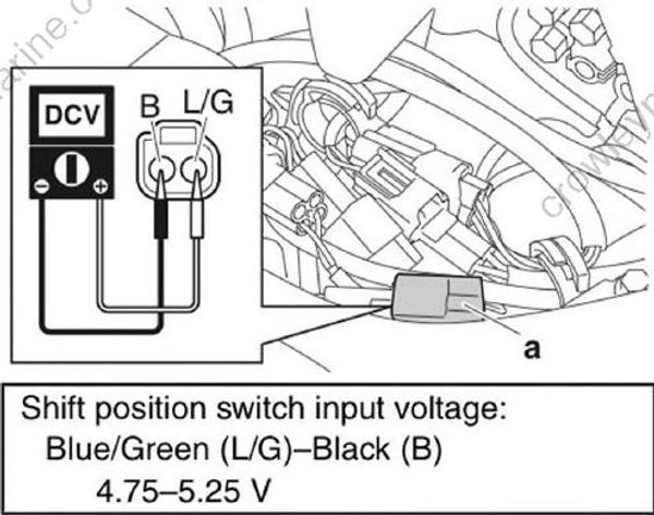
Shift position switch input voltage: Blue/Green (L/G)-Black(B) 4.75-5.25 V
Turn the engine start switch to OFF.
Remove the shift position switch.
Check the shift position switch for continuity.
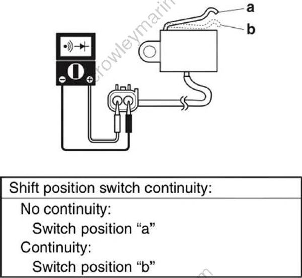
Shift position switch continuity:
No continuity: Switch position "a"
Continuity: Switch position "b"
Install the shift position switch. See “Shift rod and shift bracket” (9-15).
Connect the shift position switch .
Checking the engine shut-off switch
Disconnect the main wire harness coupler or engine start switch coupler.
Turn the engine start switch to ON, and then check the engine shut-off switch for continuity.
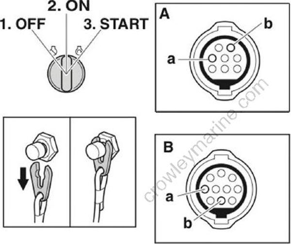
1.OFF
ON
START
A. Engine start switch
B. 703 side mount remote control
- Engine shut-off switch continuity:
Clip removed: Terminal “a”-Terminal “b”
Turn the engine start switch to OFF.
Connect the main wire harness coupler or engine start switch coupler.
Starting unit and component Checking the starter relay
Disconnect the starter relay connector “a”.
Turn the engine start switch to START position, and then measure the input volt age between the starter relay connector “a” and ground.
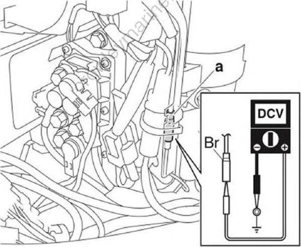
Starter relay input voltage:
Brown (Br)-Ground: 12 V (battery voltage)
- Disconnect the starter relay leads, and then remove the starter relay.
NOTICE
Before disconnecting the starter relay terminals, make sure to disconnect the negative battery terminal.
