

Preface
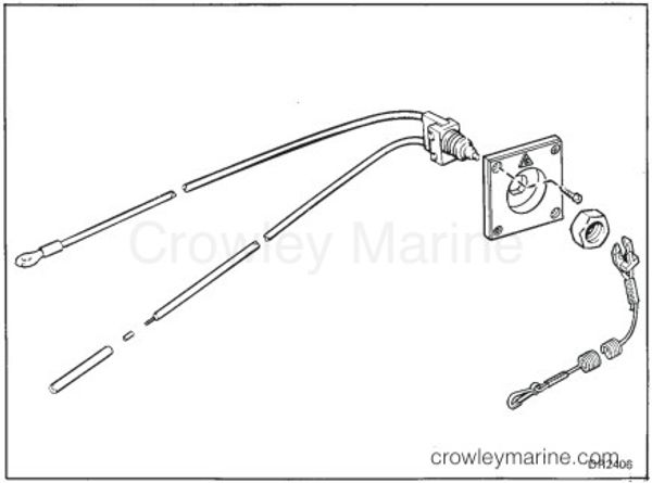
This kit permits dashboard or gunwale mounting of the Emergency Ignition Cutoff Switch for OMC® Stern Drive and OMC Cobra™ stern drive models. The emergency ignition cutoff switch is a safety device and is not a substitute for the ignition switch.
Operations To Be Performed
Step 1. Switch Installation
Step 2. Electrical Connections
Step 3. Post Installation Tests
Step 1. Switch Installation
Remove both positive and negative battery cables from battery to prevent arcing or sparks which could ignite fumes if present in the engine compartment.

[1]
Contents of Kit
| Ref. | Name of Part | Qty. |
|---|---|---|
| 1 | Cutoff Switch & Harness Assy | 1 |
| 2 | Bezel | 1 |
| 3 | Screw | 2 |
| 4 | Nut | 1 |
| 5 | Cap & Lanyard Assy | 1 |
| 6 | Wire Splice | 2 |
| 7 | Tube | 2 |
1. The emergency ignition cutoff switch lanyard is 30 inches long. Select a location near the key switch for installation of the emergency ignition cutoff switch. The lanyard must be clear of all controls and permit freedom of boat operator's arm movement when engine is in operation.
2. The mounting surface must be flat and secure and at least 5/8 in. (15 mm) thick if the screws provided are used. If the mounting surface is thinner or made of metal, Use No. 10 flat-head machine screws, flat washers, and nuts (not provided).
[2]
3. Place the bezel (2) at the selected location. Turn bezel over, face against dash, and rotate as required so hoes are at top left and bottom right. Mark switch and mounting screw holes.

[3]
4. Center punch and drill three holes with a 3/32 in. (2,4 mm) drill, and enlarge switch hole with a 1 1/2 to 2 in. (38 to 50 mm) hole saw.
[1]
5. Install switch bezel on switch (1). Install nut (4) and tighten to a torque of 28-48 in. lbs. (3-5 Nm).
[4]
6. Locate bezel with emergency ignition cutoff switch symbol (A) facing UP. Fasten bezel to mounting surface with two screws (3).
Step 2. Electrical Connections
[5]
1. Remove screw from "A" terminal (B) on ignition key switch (C). Pull instrument cable purple wire (D) away from A terminal.
[5]
2. Connect emergency ignition cutoff switch purple lead with ring terminal (E) to ignition switch "A" terminal and tighten screw securely.
[5] [6]
3. Cut ring terminal (F) off original instrument cable purple lead (D) (removed from "A" terminal). Strip 1/4 in. (6 mm) of insulation from lead. Splice instrument cable purple lead (D) to remaining emergency ignition cutoff switch lead (G) with wire splice (6) and shrink tube (7).
Step 3. Post Installation Tests
[6]
1. Attach cap (5) to the emergency ignition cutoff switch. Start and idle engine. With engine running, pull cap off switch. Engine must shut off. If engine continues to run, turn key to off position and recheck connections, correct wiring and ground connections.
To the Installer
Give these installation instructions to the future owner. The instructions contain safety warnings and other information vital to the continued safe use of the product.
Emergency Ignition Cutoff Switch Operation
The emergency ignition cutoff switch is simple to use and does not interfere with normal operating procedures. However, if the operator leaves the helm area, the cutoff switch will stop the engine. This action will prevent your boat from becoming a runaway. To restart the engine without the cap and lanyard assembly, push and hold the switch plunger. This will give emergency engine maneuvering capability.
[6]
1. The cap and lanyard assembly (5) must be attached to the switch in order to start the engine.
2. Make sure the lanyard is free to move and will not be caught or entangled on any objects during operation of the boat.
3. Attach the lanyard to a secure place on clothing. Do not attach the lanyard to any part of clothing that may be torn or will permit the lanyard to pull away rather than stop the engine.
4. Care should be taken to avoid knocking or pulling the cap off the switch during regular boating operation. Unexpected loss of forward motion could occur, causing occupants to be thrown forward.
An emergency ignition cutoff switch can be effective only if it is in working condition. Once a month perform the following:
- Check operation of emergency ignition cutoff switch. Start engine and stop by pulling lanyard. If engine does not stop, see your dealer for repairs.
- Inspect lanyard for cuts, fraying, worn cap, etc. Replace if in doubt.
The the New Owner
Retain these installation instructions with your Owner's-Operator's Manual. They contain installation, adjustment and operating information for future reference.