

YDIS
The Yamaha Diagnostic System uses precision fault diagnosis to offer better serviceability at a time when there is increasing demand for service tools for electronically controlled products.
It provides quick, reliable, safe, and reasonable service, and is intended to obtain customer satisfaction.
The Yamaha Diagnostic System features updated software and expanded tool functions that allow it to respond to new models and technologies, maintaining compatibility with regulations.
This manual contains the model-specific information. See YDIS (Ver. 2.10 or later) instruction manual for detailed information.
Basic components

| No. | Part name | Q’ty | Remarks |
|---|---|---|---|
| 1 | YDIS 2.0 Kit | 1 | LIT-YDIS2-00-KT |
| 2 | 2 2.0 CD-ROM | 1 | Software and instruction manual |
| 3 | YDIS 2.0 Adapter Module | 1 | |
| 4 | Pressure/Vacuum Sensor | 1 | |
| 5 | AD Connector Cap (adapter) | 1 | |
| 6 | AD Harness (external inputs to adapter) | 1 | |
| 7 | CAN-Harness (CL hub to adapter) | 1 | |
| 8 | K-Line Harness (motor to adapter) | 1 | |
| 9 | 12V Power Supply Harness | 1 | |
| 10 | Trigger Switch | 1 | |
| 11 | Extension Harness (trigger switch) | 1 |
Function
YDIS version 2.10 comprises the following items.

Start
Engine
Diagnosis
Diagnosis
Diagnosis Record
Engine Record
Engine operating hours by RPM
Engine Monitor
Digital Display
Graph Display
Input Setting
Component Test
Stationary Test
Active Test
Data Logger
Logger Graph
ECM Rec Graph
Logging
Record Set
Show Data
Clear Data
Engine oil change record
Boat System
Tilt Limiter
R/C System Reset
Maintenance
Check Engine
Update
Setting
Off Line
CAN Information
Communication List
Bus Statistics
4. Diagnosis
Displays diagnosis codes recorded in the engine ECM, item names, and current item conditions. This enables detection of items with problems. The trouble codes displayed are the same as those described in this chapter. See “Trouble code and checking step” (4-8).
5. Diagnosis Record
Displays diagnosis codes recorded in the engine ECM, item names, and when problems are detected. The fault diagnosis history can be erased. The trouble codes displayed are the same as those described in this chapter. See “Trouble code and checking step” (4-8).
7. Engine operating hours by RPM
Displays both operating hours and total operating hours for different engine speeds.
8. Engine Monitor
Displays engine ECM conditions (sensor information) in real time. “9. Digital Display” displays these in digital form, and “10.Graph Display” displays these in graph form. Additionally, connecting a commercially available external device and configuring “11. Input Setting” enables display of the Engine Monitor.
| Engine speed | TPS voltage | Intake air temperature |
|---|---|---|
| Intake air pressure | Throttle valve opening angle | Engine shut-off switch |
| Atmospheric pressure | ISC valve opening angle | Shift position switch |
| Ignition timing | Fuel injection duration | Oil pressure switch |
| Battery voltage | Cooling water temperature | Multi-engine system |
13. Stationary Test
When the engine is stopped and the shift is in the N position, operate the parts to check, and per form tests to check operating conditions and operating noise. Activate ignition coil
| Activate ignition coil (#1, #4) | Activate ignition coil (#2, #3) | Activate electric fuel pump *1 |
|---|---|---|
| Activate injector (#1, #4) | Activate injector (#2, #3) | Activate ISC valve |
14. Active test
While the engine is running and the shift is in the N position, operate the parts to check, and per form tests to check operating conditions and the engine condition.
| Fully open ISC valve | Fix ISC valve opening angle |
|---|
16. Logger Graph
Displays in graph form engine operation data stored in the ECM for the last 13 minutes in 1-minute intervals.
| Engine speed | TPS voltage | Intake air pressure |
|---|---|---|
| Battery voltage | Cooling water temperature | Oil pressure switch |
Engine speed
18. Logging
While the computer and the outboard motor are not connected, records “Engine Monitor'’ data using the adapter. Use “19. Record Set” to set items to record. “20. Show Data” saves logged data in the computer, and displays this data in graph form. “21. Clear Data” deletes data and conditions stored in the adapter.
22. Engine oil change record
It is possible to maintain oil change records using this function.
28. Update
It is possible to update the database when update information is provided.
29. Setting
Switches the language to use in the YDIS (English, French, Spanish, and Japanese). It is possible to select units when connected via the CAN-Line.
30. Off Line
Displays graph data saved in the Engine Monitor (Graph Display) and Logging even when the computer is not connected to the outboard motor.
Record settings for logging, deleting data, and data playback are possible even when the computer is not connected to the outboard motor.
32. Communication List
By connecting the YDIS to a multi-hub via a CAN-Line, displays the name of Yamaha genuine parts connected to the Digital Network. This enables to check that the connections are correct.
33. Bus Statistics
By connecting the YDIS to a multi-hub via a CAN-Line, displays the bus load connected to the Dig ital Network. If the bus load is higher than 40 %, then check the connection status.
Connecting the communication cable
CAN-Line
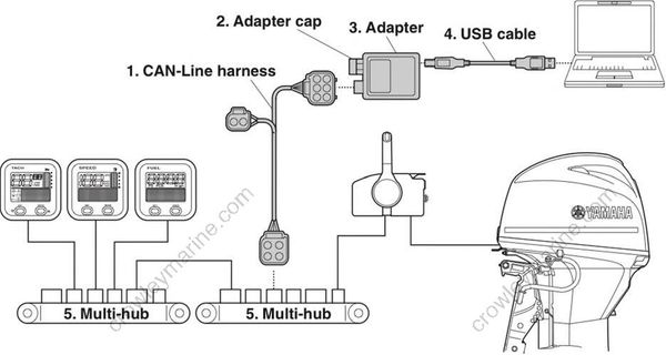
CAN-Line harness
Adapter cap
Adapter
USB cable
Multi-hub
K-Line

Adapter
Adapter cap
USB cable
K-Line harness
a. YDIS coupler (gray)
