

Preface

[1]
This kit contains the required parts to replace the shift assist switch and cable on loop-scavenged CD and CU V6, or CO thru CU V8 Outboard Models.
When the motor is shifted the switch momentarily grounds the starboard ignition system to reduce the RPM for easier gear engagement. A diode in the switch cable isolates the port ignition to prevent stalling the engine.
The switch and cable look the same as those used on later models, but have a reversed diode polarity and are not interchangeable.
We recommend this kit be installed by an authorized Johnson or Evinrude Dealer. The installation requires procedures best performed by a qualified factory trained, service technician.
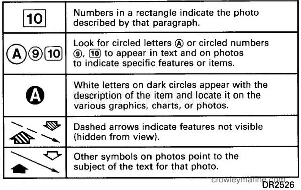
How to Read Illustration Symbols
Preparation for Installation
Read complete installation instructions prior to starting work.
Step 1. Familiarize yourself with Contents of Kit

Step 2. Remove Original Switch

Disconnect battery cables from battery before starting work. This will help prevent starter from engaging accidentally causing personal injury.
Remove starboard lower engine cover. For procedure refer to Service Manual, Powerhead Section, Powerhead Servicing.
V6 MODELS Remove shift and throttle control cable mounting nuts and washers. Remove control cables from shift and throttle levers.
[3]
ALL MODELS Remove and discard shift switch tie straps (A) (if equipped).
[4][5]
Depress mounting tabs (B) inward and pull snap bracket (C) toward you. Remove and discard bracket. (Procedure photographed with shift lever off motor for clarity.)
[6]
Grasp spring (D) and pull out of bracket. Discard spring.
[7]
Grasp switch and slider bracket assembly (E) and remove through back of shift lever cavity. Lay aside switch.
Step 3. Assemble Switch Components
[2]
Refer to Contents of Kit and select the slider bracket and spring for the model you are working on.
Apply a light even coat of Triple-Guard® 0508298 grease in grooves of slider bracket.
[8]
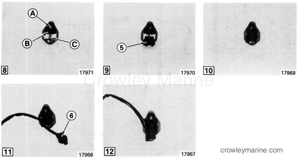
Hold actuator pin (A) in shift lever cavity and insert slider bracket (B) in shift lever cavity. Insert spring (C) in hole of slider bracket.
[9][10]
Position spring in hole of snap bracket (5). Compress spring as you seat bracket in lower edge of shift lever cavity.
[11][12]
Route switch cable down through left side of snap bracket. Align holes in switch (6) with alignment pins. Press switch against mounting tabs and switch will snap into position. Make sure switch cable does not interfere with mounting tabs.
Step 4. Remove Switch Cable

[13]
Remove electrical bracket cover mounting screw (A). Remove cover and lay aside.
[14]
Remove four electrical bracket mounting screws (B). Observe location of ground wire terminal connections and different mounting screw lengths for reassembly.
[15]
Remove starboard power pack mounting screw (C).
[16]
Pull water hoses (D) out of electrical bracket guide.
[17]
V6 MODELS Locate single-wire connector (E) on black/yellow wire at upper starboard side of powerhead. Remove clamp (if equipped) and separate plug and receptacle.
[18][19]
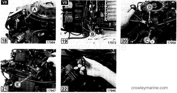
V8 MODELS Move starboard power pack aside to clear flywheel. Raise electrical bracket and locate single-wire connector (A) from black/yellow wire under bracket. Remove and discard tie strap securing switch cable to timer base wires. Separate plug and receptacle. Remove black wire terminal (B) from lower starboard crankcase screw. Remove terminal from screw and reinstall screw. Replacement switch cable black wire will be relocated to electrical bracket screw.
[20]
ALL MODELS Move starboard power pack aside. Open J-clamp (C) (if equipped) and remove switch cable. To simplify removal cut the switch cable black/yellow wire at left side of diode (D). (Flywheel removed for photo only)
[21]
Raise power pack and trace switch cable black/yellow wire to single-wire connector (E). Separate plug and receptacle. Remove and discard plug and switch cable wire that was cut off.
V6 MODELS Remove loop-clamp mounting screw on starboard side of powerhead. Remove switch cable from clamp.
[22]
ALL MODELS Remove and discard switch and cable.
Step 5. Install Replacement Switch Cable

The replacement switch cable will be routed different than the original switch cable. Follow instructions carefully to ensure correct assembly.
[23]
Route switch cable under lower engine cover mount and up powerhead. Insert into loop-clamp (if equipped) and secure with mounting screw with sufficient slack for shift lever movement.
[24]
Route switch cable up and aft of lower pump mounting boss (A) (if equipped) and under power steering reservoir (if equipped).
[25]
Route switch cable through J-clamp (B) if equipped). Insert engine plug into switch cable receptacle. Install retainer (if equipped).
[26]
Route switch cable plug under electrical bracket aft and up through bracket. Insert switch cable plug into engine receptacle (C).
Ensure switch cable and power pack wires are routed so they will not be damaged.
[27]
Position electrical bracket on powerhead. Install power pack mounting screw (D).

[28][29]
Position switch cable back wire terminal and connector clamp (A) (if equipped) on electrical bracket mounting screw. Install remaining screws and tighten securely. Insert water hoses in electrical bracket guide.
[30]
Install electrical bracket cover and mounting screw.
[31][32]
Secure switch cable to wires or hoses using tie straps (B) (not provided) to prevent damage by engine cover.
Inspect switch cable routing to ensure wires do not bind, or interfere with moving parts.
V6 MODELS Install shift and throttle control cables and secure using washers and locknuts.
ALL MODELS Install lower engine cover. Connect battery cables.
Step 6. Post Installation Tests

Launch boat. Start engine and allow to warm up.
[33]
With engine running in NEUTRAL press shift control guide DOWN at actuator pin. Engine RPM should drop indicating system is working.
STOP engine
Check switch cable routing to ensure there is not interference with moving parts.
To the Installer
Give these installation instructions to the owner. The instructions contain a list of replacement parts that are different from those listed in the motor's original parts catalog.
To the New Owner
Save these installation instructions. Stow them with your Owner's/Operator's Manual. The information and directions which were important to the original installer are just as important to the future service of the motor. The parts in this kit are different from those originally used on your motor. The part numbers of the new parts are included with these instructions.