

Step 1: EMM Servicing
IMPORTANT: If a new EMM is being installed, refer to Software on p. 95.
Step 2: Removal
Removal and installation of the EMM requires removal of the engine covers and frames.
• See Engine Cover and Frame Service on p. 55.
After covers and frames are removed from the engine continue with the procedure on the next page.
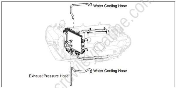
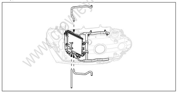
Disconnect exhaust pressure hose and water cooling hoses from EMM.
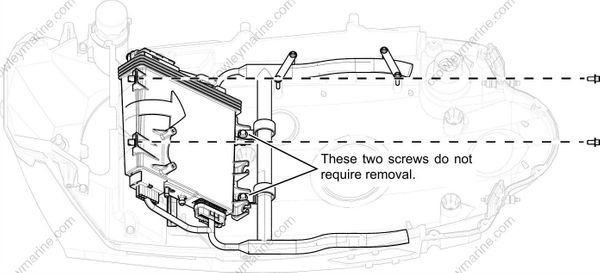
Remove EMM mounting screws (2X). Rotate EMM away from frame as shown.
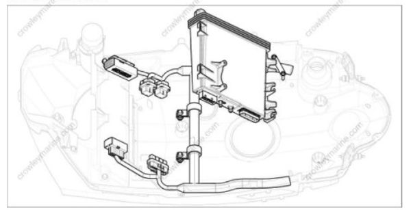
Disconnect J1-A, J1-B, J2, J3 and J4 connectors from EMM.
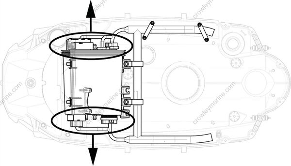
Remove EMM from frame.
Step 3: Installation
Align slots in bottom side of EMM case with isolator mounts on the frame. Slide EMM into position.
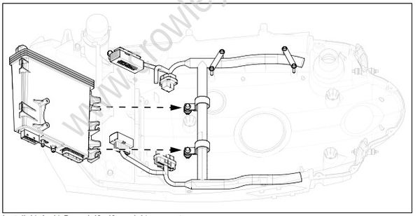
Install J1-A, J1-B, and J2, J3, and J4 connectors.
Install two EMM retaining screws. Tighten screws 12 to 16 in. lbs. (1.5 to 2 N·m).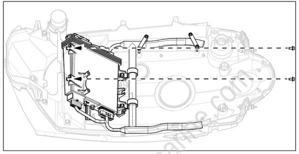
Install exhaust pressure hose and water cooling hoses. Secure each hose with one 15.7 mm Oetiker clamp, P/N 346786.
After the EMM is installed onto the center frame, install of the frames and engine covers.
• See Engine Cover and Frame Service on p. 55.
