EMM and Vapor Separator Cooling
Cooling water is routed through the EMM water cavity. Cooling of the EMM minimizes the temperatures of internal components.
Cooling water is routed to the water inlet fitting of the vapor separator water cavity. Cooling the vapor separator fuel chamber minimizes fuel vaporization.
Cooling water from the EMM and vapor separator exits through the overboard indicator. See HOSE ROUTING AND WATER FLOW DIAGRAM on p. 192
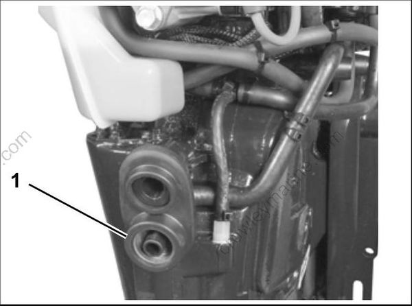
- Overboard indicator
IMPORTANT: Improper EMM cooling will activate service codes (code 29 and 25) and initiate
S.A.F.E. or SHUTDOWN. Refer to EMM DIAGNOSTICS on p. 93 for specific service code information
THERMOSTAT SERVICING
Disassembly
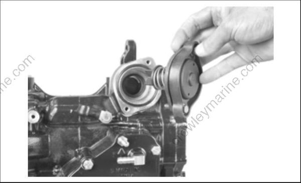
Remove the thermostat cover and O-ring from cylinder head.

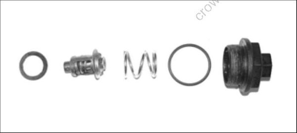
Remove spring, thermostat, and gasket.

Remove the cylinder head if cylinder head seal requires replacement. Place new seal in the cylinder head with side marked “TO CYL HEAD” facing thermostat.
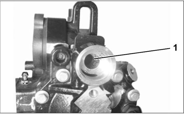
- Cylinder head
Inspection
Inspect all components for cracks, heat damage, or signs of corrosion. Replace damaged components. Clean debris from all housings and thermostat components.
Assembly
Assembly is essentially the reverse of disassembly. Pay close attention when performing the following additional tasks. Coat threads of cylinder head thermostat cover with Gasket Sealing Compound and install new O-ring. Install and tighten the cover to a torque of 120 to 144 in. lbs. (13.5 to 16 N·m).
PRESSURE RELIEF VALVE SERVICING
The pressure relief valve assembly should be serviced at the same time as the thermostat.
Disassembly
Remove pressure relief valve cover retaining screws.
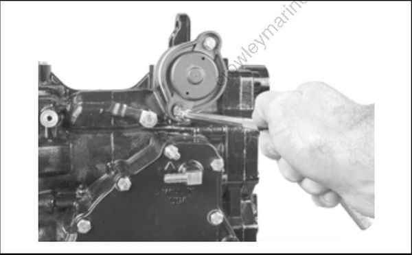
Remove the pressure relief valve assembly.