PINION BEARING
Removal/installation is in the following procedure.
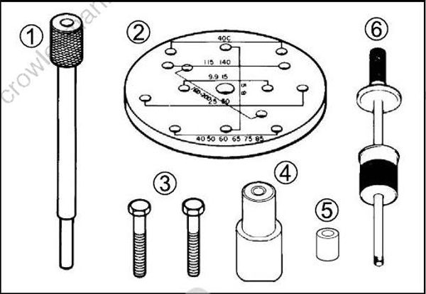
Removal & Installation Tools
09951-59910: Shaft (removal & installation) (1)
09551-39914: Plate (2)
01500-08403: Bolt (3)
09951-19421: Attachment (4)
09917-98221: Spacer (Attachment) (5)
09930-30104: Sliding hammer (6)
REMOVAL
Place the attachment 4 inside the pinion bearing.
Insert the shaft (1) into the attachment (4).
Thread the sliding hammer (6) into the top of the shaft (1).
Put a wood block under the pinion bearing.
Drive the pinion bearing out downward by striking the top of the shaft (1) with the sliding hammer (6).
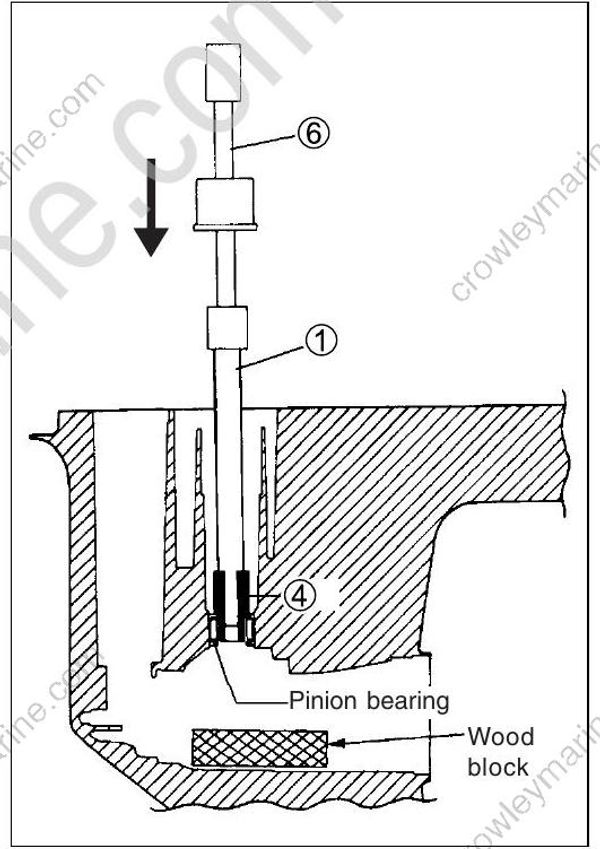
● When removing the pinion bearing, use care to avoid damaging the gearcase.
● Do not re-use the pinion bearing once removed.
Always use a new pinion bearing.
INSTALLATION
● Before installing the bearing, ensure that the inside of the gearcase is clean and free of debris.
● Ensure that the bearing stamped mark faces upward.
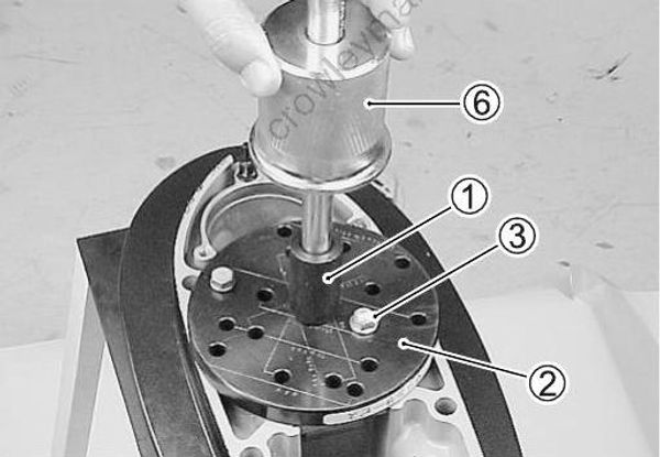
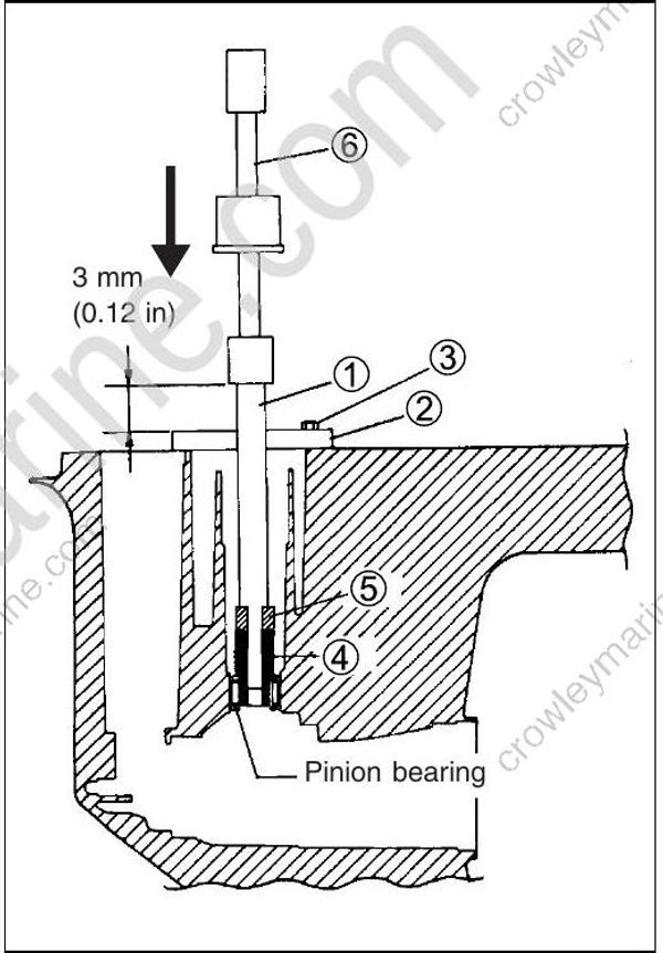
Set the shaft (1), the plate (2), the spacer (5), the attachment (4) and the pinion bearing as shown in the figure.
Place the shaft 1 (with the pinion bearing on the end of the shaft) into the gearcase.
Secure the plate (2) by tightening the bolts (3).
Thread the sliding hammer (6) into the top of the shaft (1).
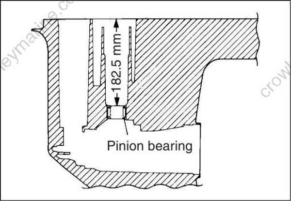
Drive the pinion bearing down into position by gently striking the shaft 1 until the dimension between the undersurface of the shaft (1) shoulder and the top surface of the plate (2) become 3 mm.