OUTLINE
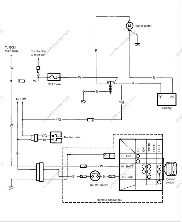
The electric starter system circuit is illustrated below. It is mainly composed of the battery, the starter motor, the relay, the neutral switches and the ignition switch.
TROUBLESHOOTING
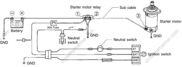
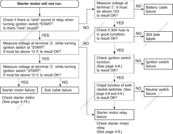
Before troubleshooting the electric starter system, make sure the followings:
• Battery is fully charged.
• All cables/wires are securely connected.
• Shift is in “NEUTRAL” position.
Circuit check schematic
INSPECTION
IGNITION SWITCH
09930-99320: Digital tester
Tester range: (Continuity)
Shift into NEUTRAL.
Disconnect the remo-con box wire harness connector from the engine side.
Inspect continuity between the wires while operating the switch key.
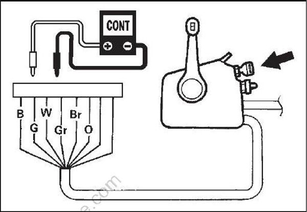
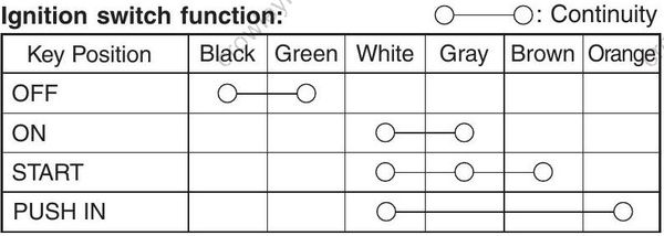
If the result is out of the specification, replace the ignition switch.
EMERGENCY STOP SWITCH
The steps for this inspection are the same as “IGNITION SWITCH” section except for tester probe connection.
Inspect continuity between the Green wire and the Black wire.
Emergency stop switch function:
| Switch plate position | Continuity |
|---|---|
| Plate IN | No |
| Plate OUT | Yes |
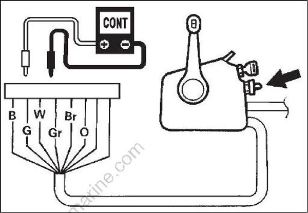
If the result is out of the specification, replace the emergency stop switch.
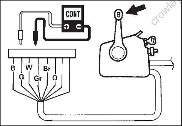
NEUTRAL SWITCH
Neutral switch in remo-con box
The steps for this inspection are the same as “IGNITION SWITCH” section except for tester probe connection.
Inspect continuity between the Brown wire and the White wire while operating the remo-con handle.
Neutral switch function:
| Shift position | Continuity |
|---|---|
| Neutral | Yes |
| Forward | No |
| Reverse | No |
If the result is out of the specification, replace the neutral switch.
Neutral switch on cylinder block
09930-99320: Digital tester
Tester range: (Continuity)
Disconnect the neutral switch wire located in the electric parts holder.
Inspect continuity between the Yellow/Green wire and the Brown wire while operating the remo-con handle.
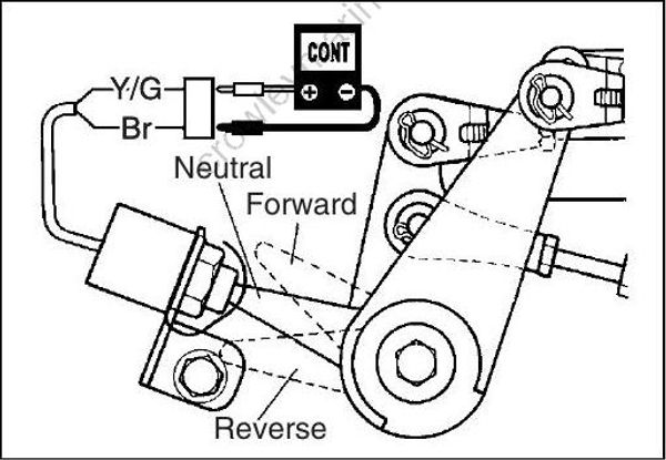
Neutral switch function:
| Shift position | Continuity |
|---|---|
| Neutral | Yes |
| Forward | No |
| Reverse | No |
If the result is out of the specification, replace the neutral switch.
STARTER MOTOR RELAY
09930-99320: Digital ester
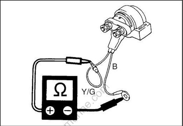
Disconnect all cables/wires from the starter motor relay.
Resistance check
Tester range: Ω (Resistance)
Measure resistance between the Yellow/Green wire and the Black wire.
Starter motor relay resistance: 3.5 – 5.1 Ω
If the resistance is out of the specification, replace the starter motor relay.
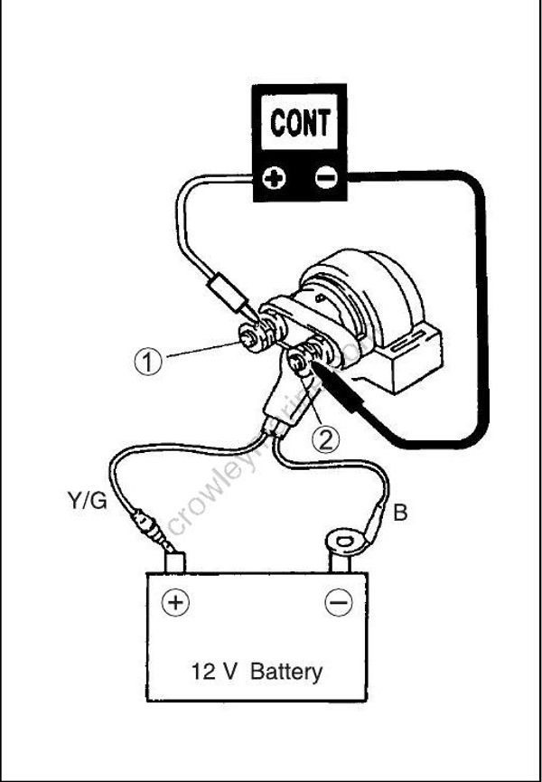
Function check
Tester range: (Continuity)
Inspect continuity between the terminal 1 and 2 with momently applying 12 V power. Connect the Yellow/Green wire to the positive (+) terminal, and the Black wire to the negative terminal of the battery.
Starter motor relay function:
| 12 V power | Continuity |
|---|---|
| Applied | Yes |
| Not applied | No |
If the result is out of the specification, replace the starter motor relay.
STARTER MOTOR
REMOVAL
Before removing starter motor:
- Disconnect battery cables from battery.
- Remove the screw and the flywheel cover.
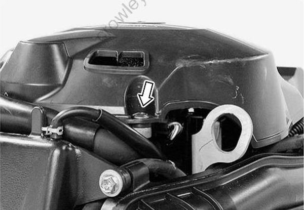
Remove the breather hose and the evaporation hose.
Remove the bolt, the fastening band and the silencer cover.
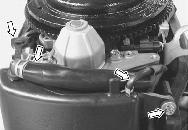
Disconnect the lead wire connectors from the IAT sensor, the IAC valve and the CTP switch.
Disconnect the throttle linkage rod.
Remove the flame arrester and the seal rubber.
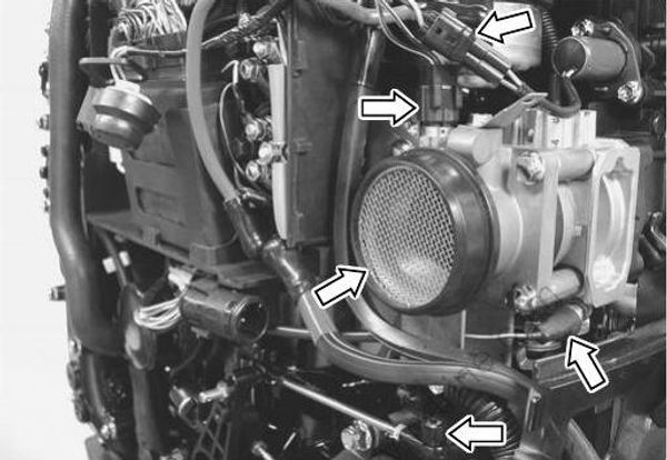
- Remove the six silencer/throttle body securing bolts.
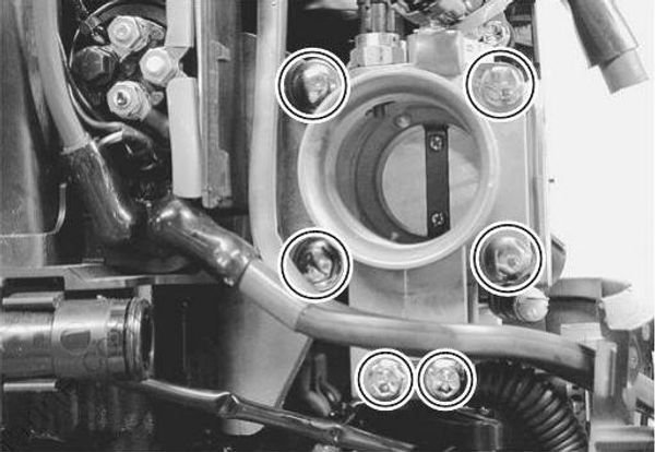
Loosen the two silencer bracket bolts.
Remove the silencer and the throttle body.
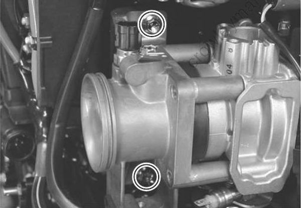
Remove the starter motor sub cable.
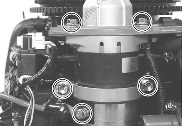
Remove the four bolts, the motor band and the starter motor assy.
INSTALLATION
Installation is reverse order of removal with the special attention to the following steps.
- Install the starter motor and tighten the four starter motor mounting bolts securely.
Starter motor mounting bolt: 23 N·m (2.3 kg-m, 16.5 Ib-ft)
- Install the silencer and the throttle body to the intake manifold with the six bolts first, then tighten the two silencer bracket bolts.
DISASSEMBLY
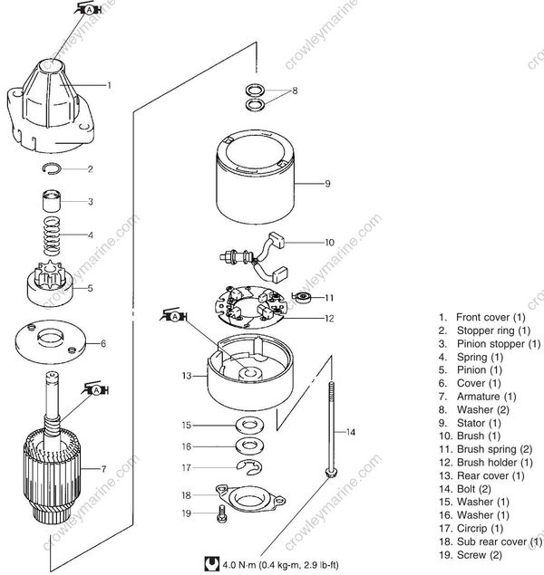
For correct assembly, scribe an alignment mark on the front cover, the stator and the rear cover.

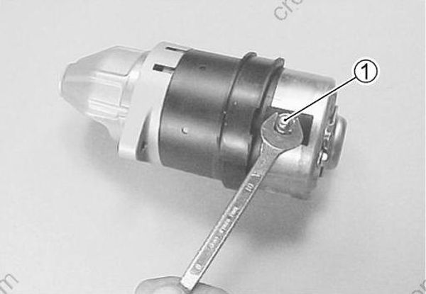
- Remove the nut (1) on the (+) terminal.
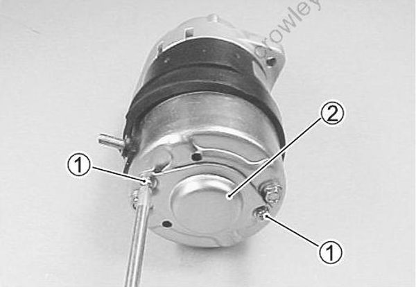
- Remove the two screws 1 and the sub rear cover (2).
- Remove the circlip (1), the washer (2) and (3).
When installing, set the thicker washer 3 to the circlip side

- Remove the two bolts (1).
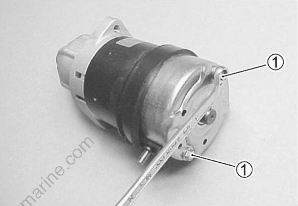
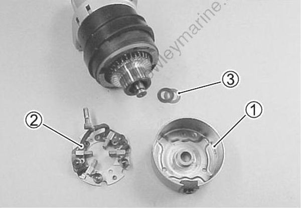
Remove the rear cover (1) and the brush holder (2).
Remove the two washers (3) from the armature shaft.
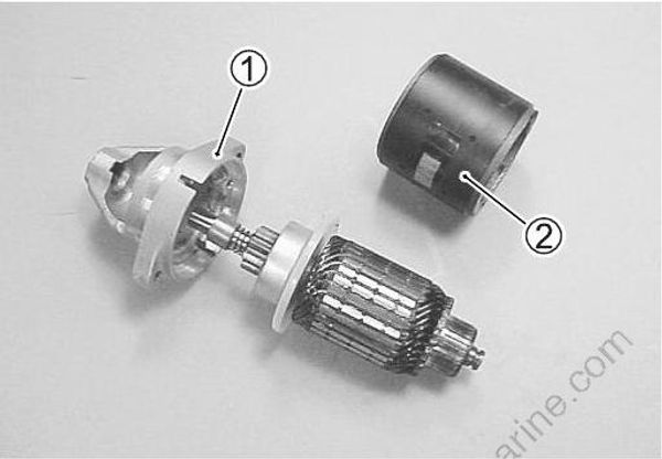
- Remove the front cover (1) and the stator (2).
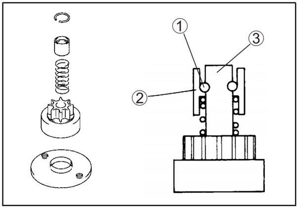
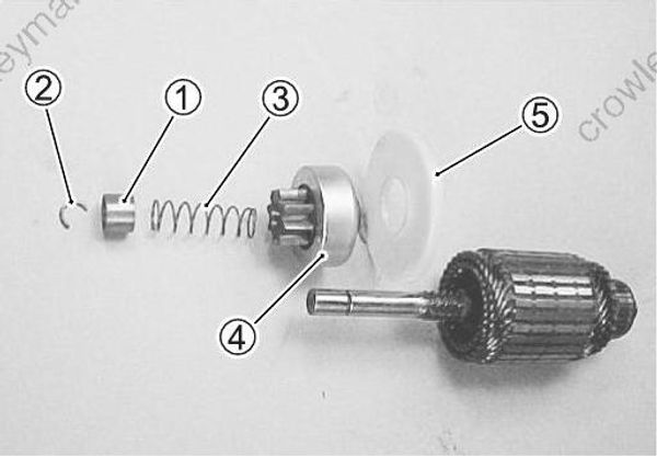
Push down the pinion stopper (1), remove the stopper ring (2).
Remove the pinion stopper (1), the spring (3), the pinion (4) and the cover (5).
Wear safety grasses when disassembling and assembling stopper ring.
Using a screw-driver, pry off the stopper ring.
INSPECTION & SERVICING
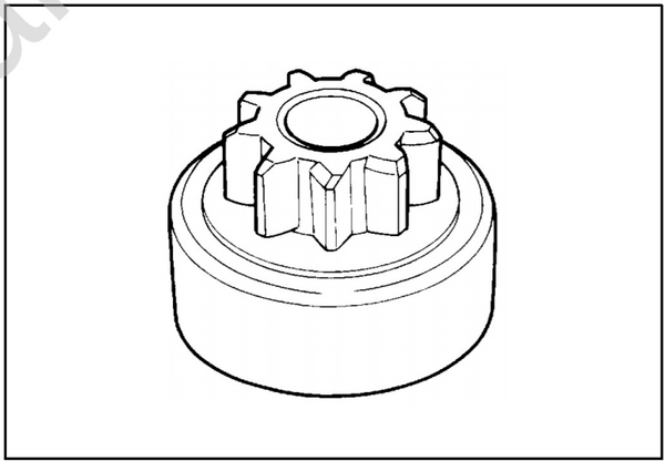
Pinion
Inspect the pinion.
If excessive wear or other damage is found, replace the pinion.
Armature and Commutator
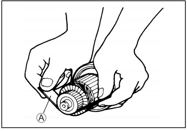
- Inspect the commutator surface.
If the surface is gummy or dirty, clean with 400 grade emery paper (A).
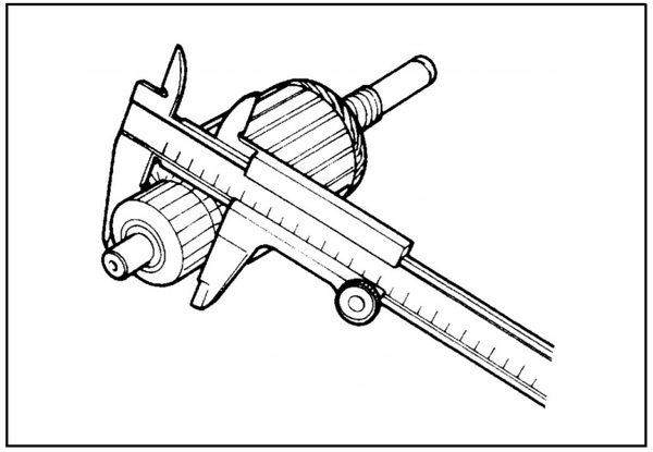
- Measure the commutator outside diameter.
09900-20101: Vernier calipers
Commutator outside diameter:
Standard: 33.0 mm (1.30 in)
Service limit: 32.0 mm (1.26 in)
If the measurement exceeds the service limit, replace the armature.
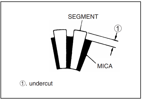
- Check that the mica (insulator) between the segments is undercut to the specified depth.
Commutator undercut:
Standard: 0.5 – 0.8 mm (0.02 – 0.03 in)
Service limit: 0.2 mm (0.01 in)
If the measurement exceeds the service limit, cut to the specified depth.
Remove all particles of mica and metal using compressed air
Wear safety grasses when using compressed air.
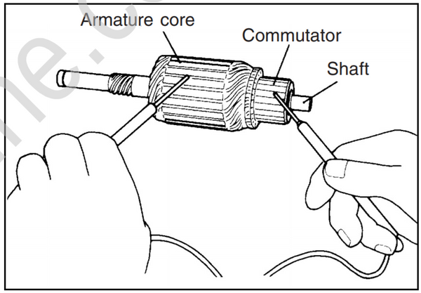
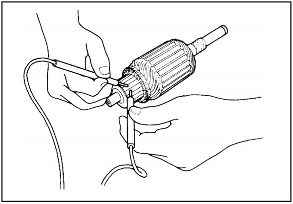
- Inspect continuity of the armature coil.
09930-99320: Digital tester
Tester range: (Continuity)
Armature coil continuity
| Tester probe connection | Continuity |
|---|---|
| Between commutator segments | Yes |
| Commutator to Armature core | No |
| Commutator to Shaft | No |
If the result is out of the specification, replace the armature.
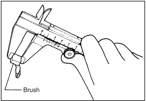
Brushes
Measure length of each brush.
09900-20101: Vernier calipers
Brush length:
Standard: 17.0 mm (0.67 in)
Service limit: 10.0 mm (0.39 in)
If the measurement exceeds the service limit, replace the brush.
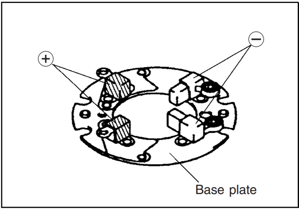
Brush Holder
Inspect continuity of the brush holder.
09930-99320: Digital tester
Tester range: (Continuity)
| Tester probe connection | Continuity |
|---|---|
| Brush holder positive (+) to Brush holder negative (- | ) No |
| Brush holder positive (+) to Base plate (ground) | No |
If the result is out of the specification, replace the brush holder.
ASSEMBLY
Assembly is reverse of disassembly with the special attention to the following steps.
When installing armature, exercise care to avoid breaking brushes.
- Apply the grease to the armature shaft and the shaft holes.
99000-25010: SUZUKI SUPER GREASE “A”
- Align the front cover, the stator and the rear cover with the alignment lines scribed earlier and assemble the starter motor.
Through bolt: 4.0 N·m (0.4 kg-m, 2.9 Ib-ft)
Wear safety grasses when disassembling and reassembling stopper ring.
- Install the pinion, the spring, the pinion stopper and the stop per rings.
Make sure that the stopper rings (1) tightly fit in the pinion stopper (2) and the armature shaft (3).