REMOVAL
Before removing the cylinder head assy:
• Remove the power unit. (See page 6-6.)
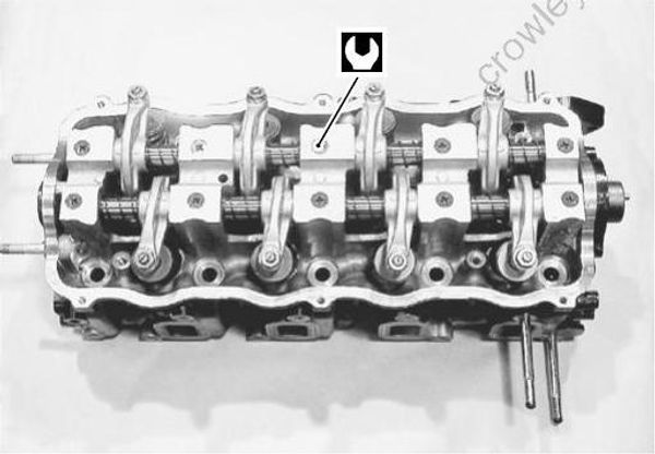
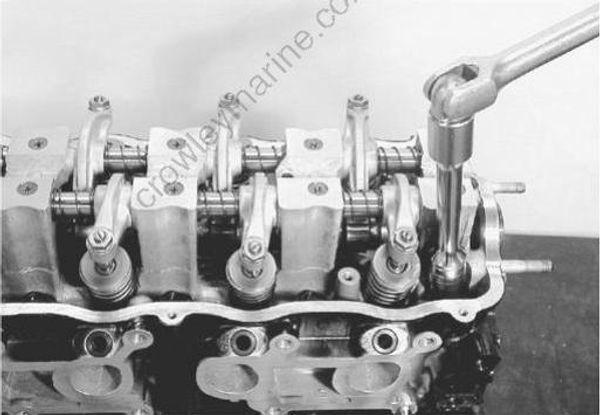
Remove the ten bolts.
Remove the cylinder head assy and the gasket.
INSTALLATION
Installation is reverse order of removal with the special attention to the following steps.
Do not re-use the gasket once removed. Always use a new gasket.
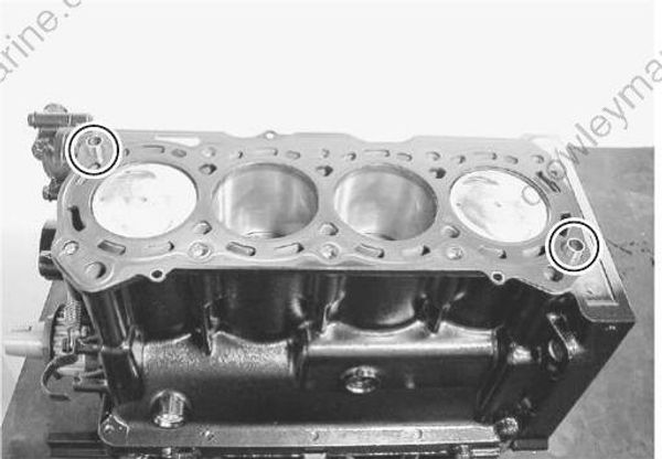
Install the gasket and the two dowel pins.
Install the cylinder head to the cylinder block.
Apply engine oil lightly to the cylinder head bolts.
Tighten the bolts to 50 percent (%) of the specified torque according to the numerical order in the figure.
Cylinder head bolt (50% torque):
1st step 37 N·m (3.7 kg-m, 27.0 lb-ft)
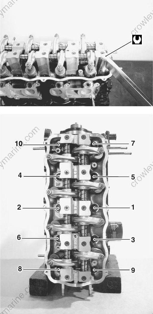
Loosen all bolt to 0 N·m (0 kg-m, 0 lb-ft) according to the reverse order. (2nd step)
Finally tighten the bolts to the specified torque in two steps according to the numerical order in the figure.
Cylinder head bolt:
3rd step 37 N·m (3.7 kg-m, 27.0 lb-ft)
Final step 73 N·m (7.3 kg-m, 53.0 lb-ft)
DISASSEMBLY
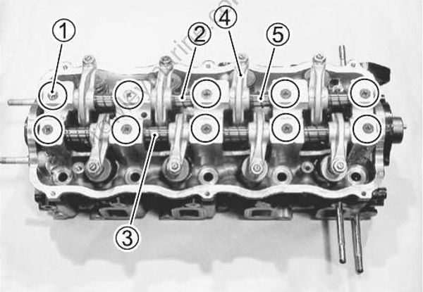
Remove the ten screws (1).
Remove the intake rocker arm shaft (2) and the exhaust rocker arm shaft (3).
Remove all rocker arms (4) and all springs (5).
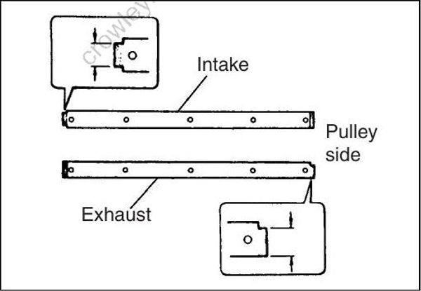
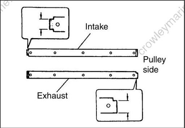
The intake rocker arm shaft differs from the exhaust one in shape as shown.
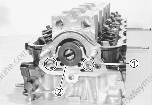
- Remove the two bolts (1) and the camshaft thrust plate (2).
- Remove the oil seal using the special tool.
09913-50121: Oil seal remover
- Remove the camshaft pulling toward the pulley side.
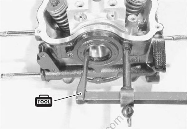
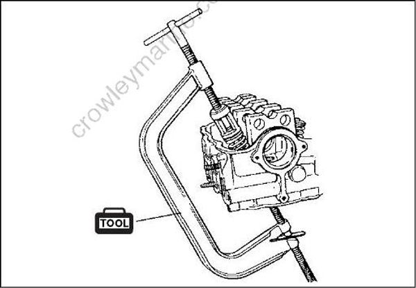
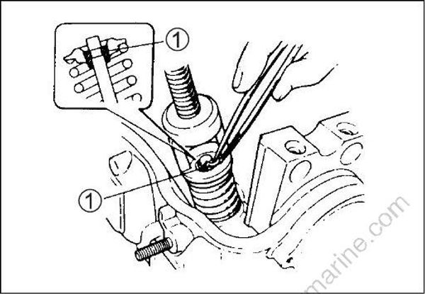
Remove the valve cotters (1) while compressing the valve spring.
Remove the valve spring retainer (2), the valve spring (3) and the valve (4).
09916-14510: Valve lifter
09916-48210: Attachment
09916-84511: Tweezers
Reassemble each valve and valve spring to their original positions.
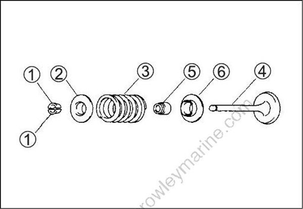
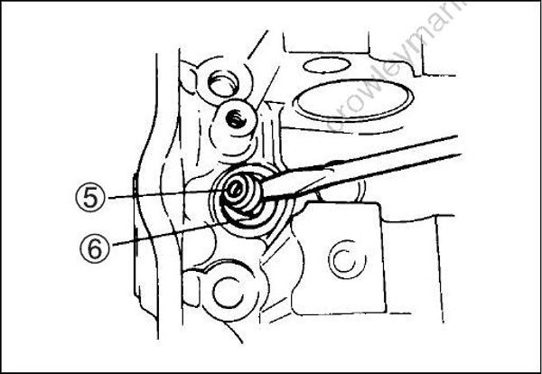
- Remove the valve stem seal 5 and the valve spring seat 6.
INSPECTION/SERVICING
If crack, excessive wear or other damage is found on any component, replace.
CYLINDER HEAD
- Remove all carbon from the combustion chamber.
• Do not use any sharp edged tool to scrape carbon off the cylinder head or the head components.
• Be careful not to scuff or nick the metal surfaces when decarboning.
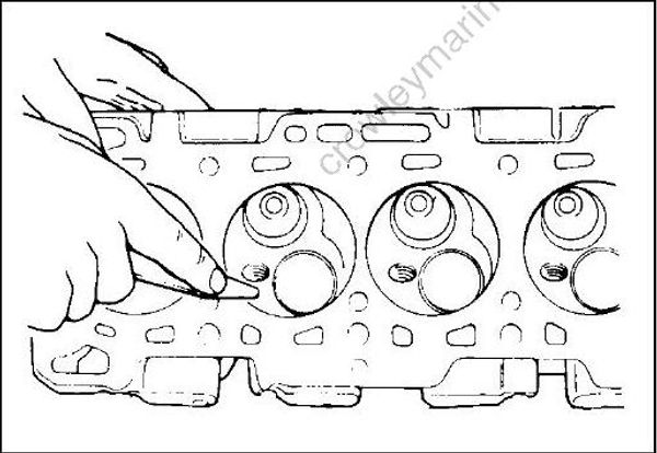
- Inspect the intake ports, the exhaust ports, the combustion chambers and the head surface.
If crack or other damage is found, replace the cylinder head.
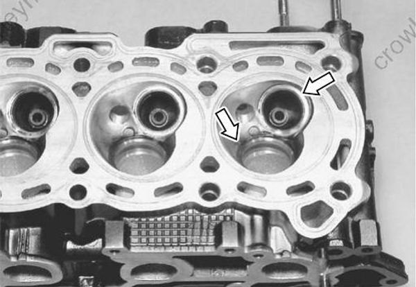
Valve seat
Check the valve seat.
If crack or other damage is found, replace the cylinder head.
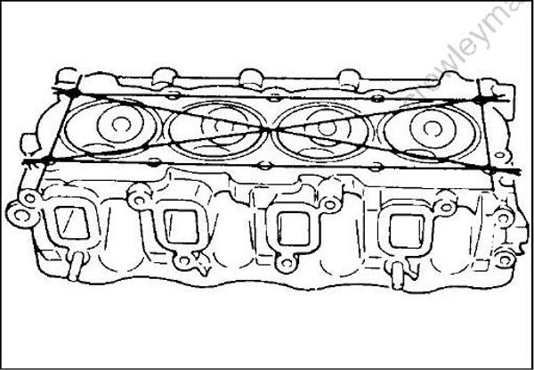
Cylinder head distortion
Measure the cylinder head distortion (gasketed surface) at a total of 6 locations as shown.
09900-20803: Thickness gauge
Straight gauge
Service limit: 0.05 mm (0.002 in)
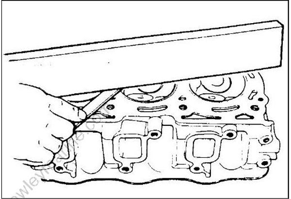
If the measurement exceeds the service limit, resurface or replace the cylinder head.
The cylinder head can be resurfaced, using a surface plate and #400 grit wet sandpaper. Move the cylinder head in a figure eight pattern when sanding
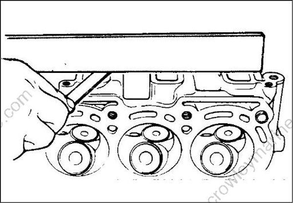
Intake manifold seating faces distortion
Measure the intake manifold seating faces distortion.
09900-20803: Thickness gauge
Straight gauge
Service limit: 0.10 mm (0.004 in)
If the measurement exceeds the service limit, resurface or replace the cylinder head.
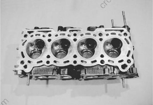
Water jackets
Inspect the water jackets.
If clog or obstruction is found, clean the water jacket.
CAMSHAFT
Cam height
Measure the cam height (H).
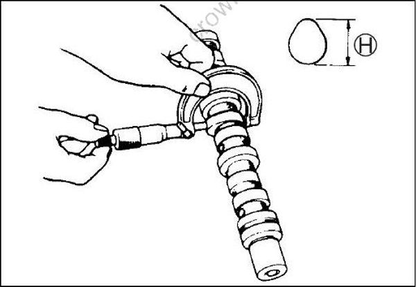
Standard:
DF60 IN 38.061 – 38.221 mm (1.4985 – 1.5048 in)
EX 38.059 – 38.219 mm (1.4984 – 1.5047 in)
DF70 IN 37.631 – 37.791 mm (1.4815 – 1.4878 in)
EX 37.629 – 37.789 mm (1.4815 – 1.4878 in)
Service limit:
DF60 IN 37.961 mm (1.4945 in)
EX 37.959 mm (1.4944 in)
DF70 IN 37.531 mm (1.4776 in)
EX 37.529 mm (1.4775 in)
If the measurement exceeds the service limit, replace the cam shaft.
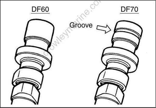
Camshaft identification
| DF60 | Without groove |
|---|---|
| DF70 | With groove |
Camshaft runout
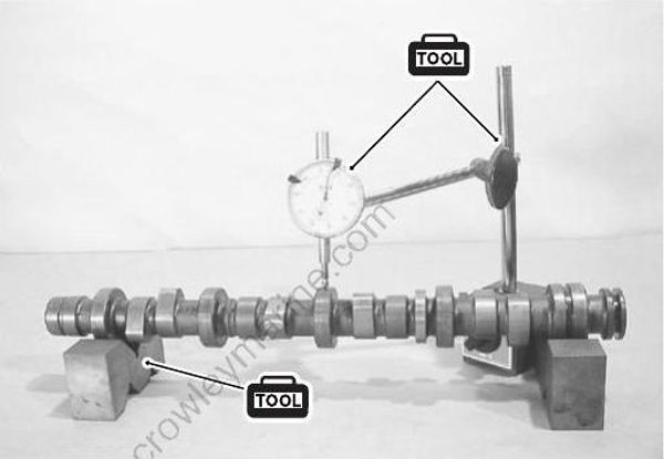
Measure the camshaft runout.
09900-20602: Dial gauge
09900-20701: Magnetic stand
09900-21304: Steel “V” block set
Service limit: 0.10 mm (0.004 in)
If the measurement exceeds the service limit, replace the cam shaft.
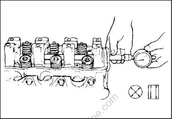
Camshaft journal oil clearance
Standard: 0.050 – 0.091 mm (0.0020 – 0.0036 in)
Service limit: 0.150 mm (0.0059 in)
If the measurement exceeds the service limit, replace the cam shaft and/or the cylinder head.
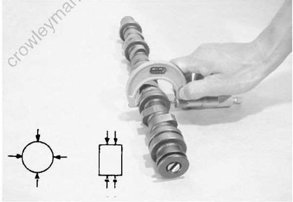
To check the clearance, measure the following items:
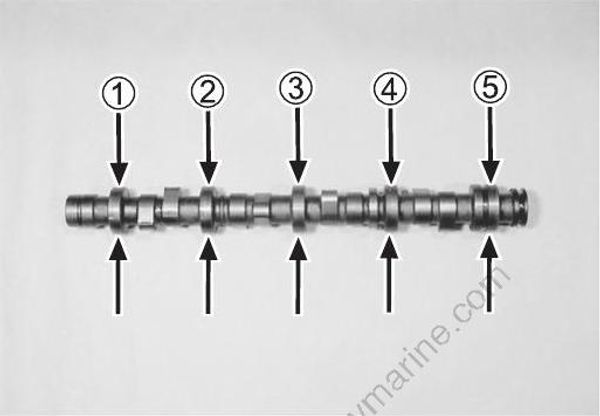
Camshaft journal outside diameter (5 locations)
Camshaft holder inside diameter (5 locations)
09900-20202: Micrometer
Small bore gauge or Dial calipers
Standard:
| Position | Camshaft journal outside diameter | Camshaft holder inside diameter |
|---|---|---|
| (1) | 44.925 – 44.950 mm (1.7687 – 1.7697 in) | 45.000 – 45.016 mm (1.7717 – 1.7723 in) |
| (2) | 44.725 – 44.750 mm (1.7608 – 1.7618 in) | 44.800 – 44.816 mm (1.7638 – 1.7644 in) |
| (3) | 44.525 – 44.550 mm (1.7530 – 1.7539 in) | 44.600 – 44.616 mm (1.7559 – 1.7565 in) |
| (4) | 44.325 – 44.350 mm (1.7451 – 1.7461 in) | 44.400 – 44.416 mm (1.7480 – 1.7487 in) |
| (5) | 44.125 – 44.150 mm (1.7372 – 1.7382 in) | 44.200 – 44.216 mm (1.7402 – 1.7408 in) |
ROCKER ARM/SHAFT
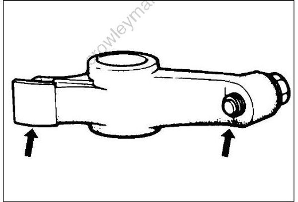
Rocker arm wear
Inspect the arm-riding face and the tip of the adjusting screw.
If excessive wear is found, replace the rocker arm and/or the adjusting screw.
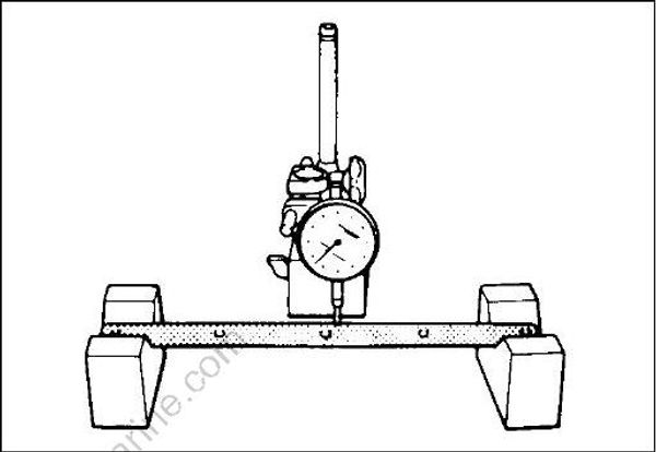
Rocker arm shaft runout
09900-20602: Dial gauge
09900-20701: Magnetic stand
09900-21304: Steel “V” block set
Service limit: 0.12 mm (0.005 in)
If the measurement exceeds the service limit, replace the rocker arm shaft.
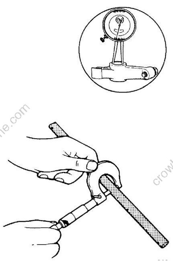
Rocker arm shaft to rocker arm clearance
Standard: 0.012 – 0.045 mm (0.0005 – 0.0018 in)
Service limit: 0.090 mm (0.0035 in)
If the measurement exceeds the service limit, replace the rocker arm and/or the rocker arm shaft.
To check the clearance, measure the following items:
Rocker arm shaft outside diameter
Rocker arm inside diameter
09900–20205: Micrometer
09900–20605: Dial calipers
Standard:
| Rocker arm shaft outside diameter | Rocker arm inside diameter |
|---|---|
| 15.973 – 15.988 mm (0.6289 – 0.6294 in) | 16.000 – 16.018 mm (0.6299 – 0.6306 in) |
VALVE/VALVE GUIDE
Valve guide to valve stem clearance
Standard: IN 0.020 – 0.050 mm (0.0008 – 0.0020 in)
EX 0.045 – 0.075 mm (0.0018 – 0.0030 in)
Service limit: IN 0.070 mm (0.0028 in)
EX 0.090 mm (0.0035 in)
If the measurement exceeds the service limit, replace the valve and/or the valve guide.
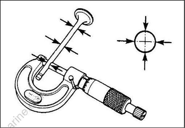
To check the clearance, measure the following items:
Valve stem outside diameter
Valve guide inside diameter
09900-20205: Micrometer
Small bore gauge or Dial calipers
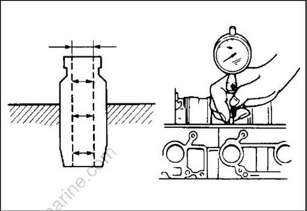
Standard:
| Valve stem outside diameter | Valve guide inside diameter | |
|---|---|---|
| IN | 6.965 – 6.980 mm (0.2742 – 0.2748 in) | 7.000 – 7.015 mm (0.2756 – 0.2762 in) |
| EX | 6.940 – 6.955 mm (0.2732 – 0.2738 in) | 7.000 – 7.015 mm (0.2756 – 0.2762 in) |
If you are unable to measure the valve guide inside diameter, measure the “Valve stem end deflection”.
Valve stem end deflection
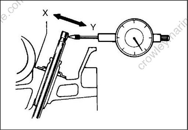
Measure the valve stem end deflection as follows:
Install the valve into the valve guide.
Position the valve head at approx. 10 mm away from the valve seat.
Move the stem end in the direction “X – Y”, and measure the deflection.
09900-20602: Dial gauge
09900-20701: Magnetic stand
Service limit: IN 0.14 mm (0.006 in)
EX 0.18 mm (0.007 in)
If the measurement exceeds the service limit, replace the valve. If the measurement still exceeds the service limit with a new valve, replace the valve guide.
For the valve guide replacement, see the “VALVE GUIDE REPLACEMENT” section on the page 6-23.
Valve stem end length
Measure the valve stem end length (1).
09900-20102: Vernier calipers
Service limit: IN & EX 6.05 mm (0.238 in)
If the measurement exceeds the service limit, replace the valve.

Valve stem runout
Measure the valve stem runout.
09900-20602: Dial gauge
09900-20701: Magnetic stand
09900-21304: Steel “V” block set
Service limit: IN & EX 0.05 mm (0.002 in)
If the measurement exceeds the service limit, replace the valve.
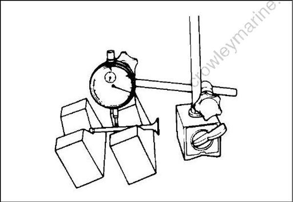
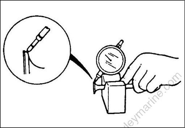
Valve head radial runout
Measure the valve head radial runout.
09900-20602: Dial gauge
09900-20701: Magnetic stand
09900-21304: Steel “V” block set
Service limit: IN & EX 0.08 mm (0.003 in)
If the measurement exceeds the service limit, replace the valve.
Valve head thickness
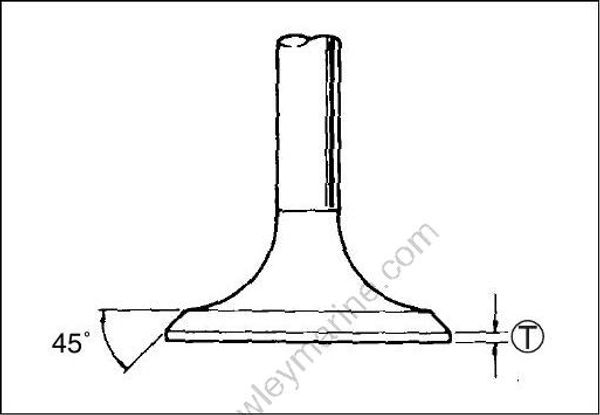
Measure the valve head thickness (T).
09900-20102: Vernier Calipers
Standard: IN & EX 1.0 mm (0.04 in)
Service limit: IN 0.6 mm (0.02 in)
EX 0.7 mm (0.03 in)
If the measurement exceeds the service limit, replace the valve.
Valve seating contact width
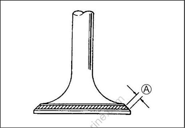
Measure the valve seating contact width (A) as follows:
Coat the valve seat evenly with Prussian blue (or equivalent).
Install the valve into the valve guide.
Put the valve lapper on the valve.
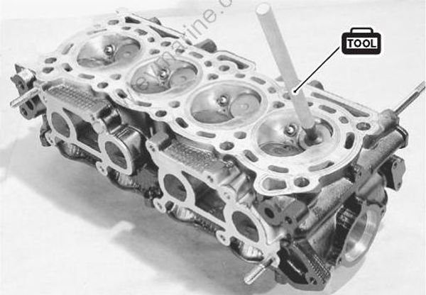
09916-10911: Valve lapper
Rotate the valve while gently tapping the valve contact area against the seat.
Continuously pattern on the valve seating face with Prussian blue.
Measure the valve seating contact width A.
09900-20102: Vernier calipers
Standard: IN & EX 1.3 – 1.5 mm (0.05 – 0.06 in)
If the measurement is out of the specification, service the valve seat.
For the valve seat servicing, see the “VALVE SEAT SERVICING” section on the page 6-24.
VALVE GUIDE REPLACEMENT
Be careful not to damage the cylinder head when replacing the valve guide.
- Drive the valve guide out toward the valve spring side.
09916-44511: Valve guide remover/installer
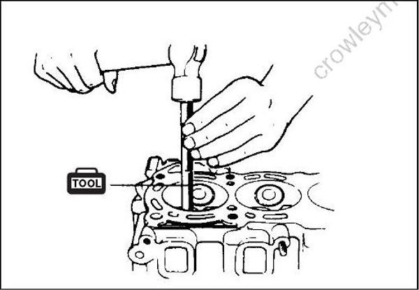
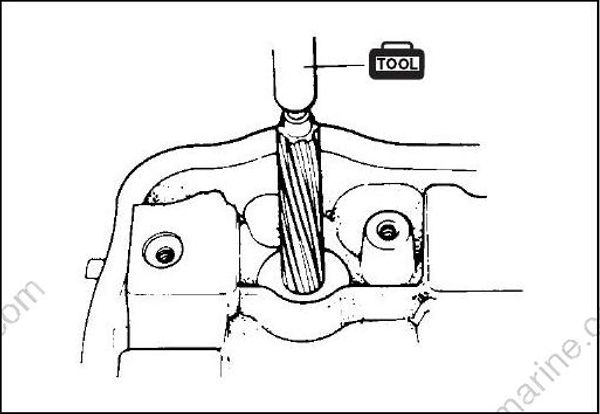
- Refinish the valve guide hole.
09916-37310: Valve guide reamer (12 mm)
09916-34542: Valve guide reamer handle
Turn the reamer clockwise, never counterclockwise.
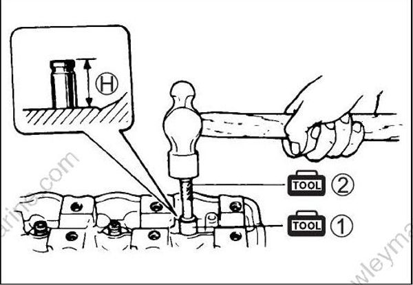
- Drive in the valve guide until the tool (1) contacts the cylinder head.
09917-88210: Valve guide installer attachment – (1)
09916-57321: Valve guide installer – (2)
- Measure the valve guide protrusion (H).
09900-20102: Vernier calipers
Valve guide protrusion:
Standard: IN & EX 14.0 mm (0.55 in)
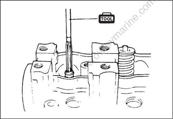
- Refinish the valve guide bore.
09916-34520: Valve guide reamer (7 mm)
09916-34542: Valve guide reamer handle
Clean and oil the valve guide bore when reamed.
VALVE SEAT SERVICING
If the valve seating contact width is out of the specification, reface the valve seat as follows:
09916-24940: Solid pilot (N-150-7)
09916-54910: Handle (N-505)
09916-24935: Valve seat cutter (N-608)
09916-24910: Valve seat cutter (N-212)
Turn the cutter clockwise, never counterclockwise.
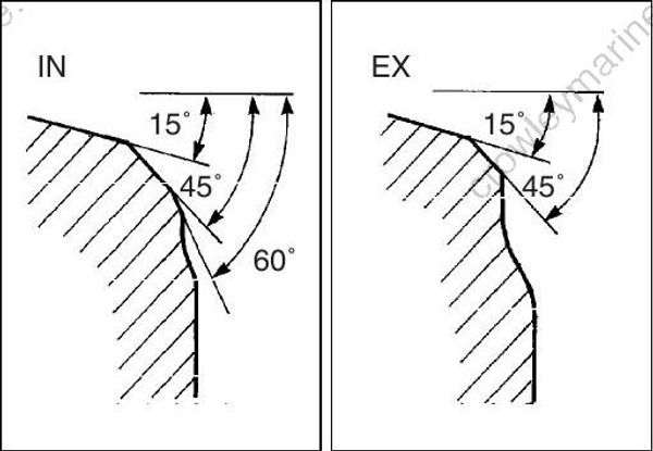
Insert the 45° cutter and reface the valve seat.
Measure the valve seating contact width (A). See the “Valve seating contact width” section on the page 6-23.
If the width (A) is too high (or wide), reface the valve seat using the 15° cutter.
If the width (A) is too low (or narrow), reface the valve seat using the 45° cutter.
- Clean up any burrs using the 45° cutter very lightly.
Grind the seat areas minimally only.
Do not grind more than necessary.
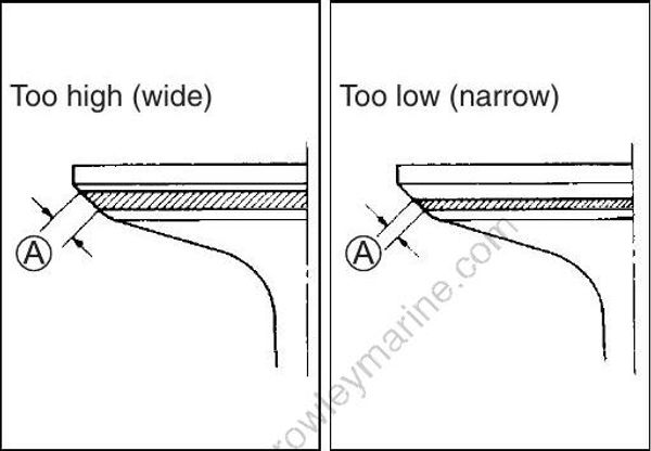
- Recheck the valve seat contact width (A).
Do not use lapping compound after the final cut is made. The finished valve seat should have a velvety smooth finish and not a highly polished or shiny finish. This will provide a soft surface for the final seating of the valve which will occur during the first few
seconds of engine operation.
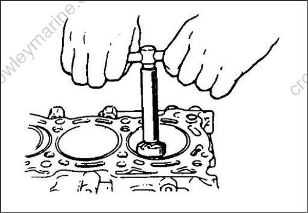
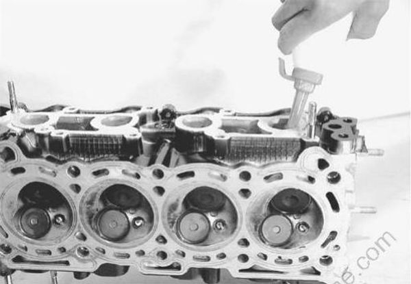
Clean and assemble the cylinder head and the valve components. Fill the intake and the exhaust ports with solvent to check for leaks between the valve seat and the valve. If any leaks occur, inspect the valve seat and the face for burrs or other things that could prevent the valve from sealing
VALVE SPRING
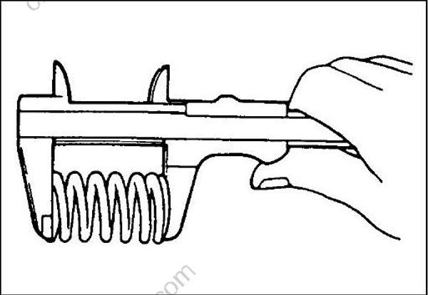
Valve spring free length
Measure the spring free length.
09900-20102: Vernier calipers
Standard: 49.3 mm (1.94 in)
Service limit: 48.1 mm (1.89 in)
If the measurement is the lower than the service limit, replace the valve spring.
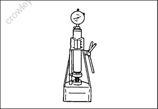
Valve spring tension
Measure the valve spring tension.
09900-20102: Vernier caliper
Standard: 24.8 – 29.2 kg (54.7 – 64.3 lbs) for 41.5 mm (1.63 in)
Service limit: 22.8 kg (50.2 lbs) for 41.5 mm (1.63 in)
If the measurement is the lower than the service limit, replace the valve spring.
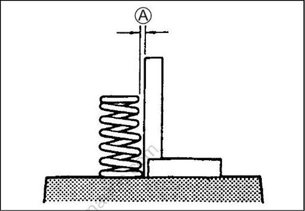
Valve spring sequareness
Measure the valve spring sequareness (A).
09900-20102: Vernier calipers
Sequare plate
Service limit: 2.0 mm (0.08 in)
If the measurement exceeds the service limit, replace the valve spring.
REASSEMBLY
Reassembly is reverse order of disassembly with the special attention to the following steps.
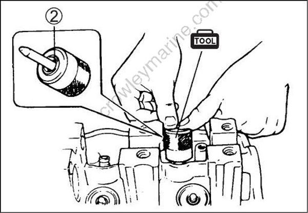
Install the valve spring seat (1).
Apply the engine oil to the valve stem seal (2).
Install the valve stem seal onto the valve guide by pushing the tool with finger tip.
09917-98210: Valve stem seal installer
Do not re-use the seal once removed. Always use a new seal.
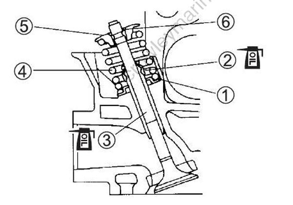
Apply the engine oil to the stem seal, the valve guide bore and the valve stem.
Install the valve (3), the valve spring (4), and the valve retainer (5).
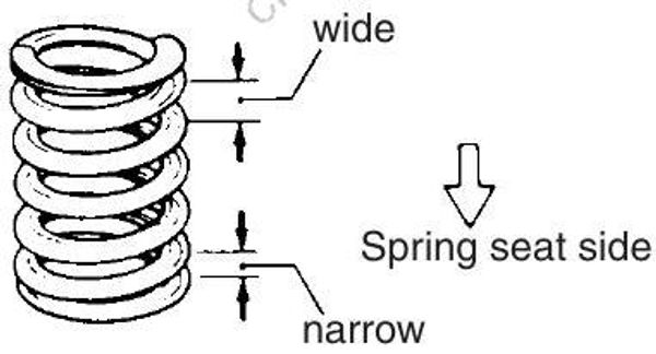
• Reassemble each valve and valve spring to their original position.
• Set the valve spring in place with the narrow spiral area facing the valve spring seat.
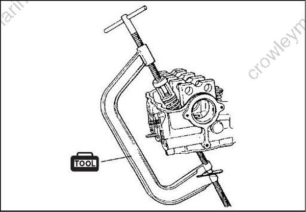
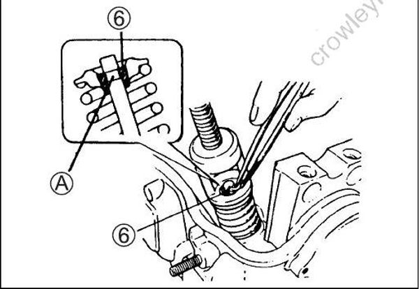
Install the valve cotters (6) while compressing the valve spring by the tool.
Make sure the valve cotters seat in the groove A properly.
09916-14510: Valve lifter
09916-48210: Attachment
09916-84511: Tweezers
CAMSHAFT
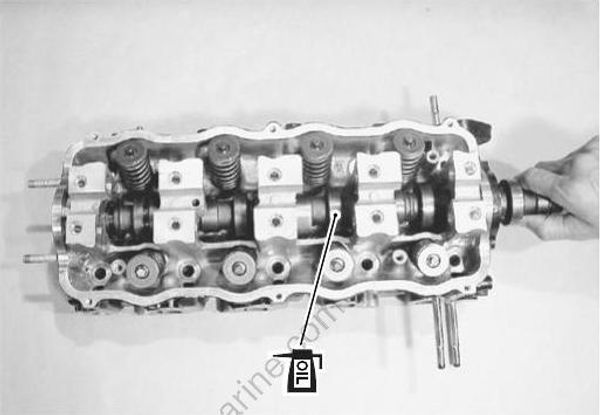
Apply the engine oil to the camshaft and all holder journals.
Install the camshaft from the camshaft pulley side.
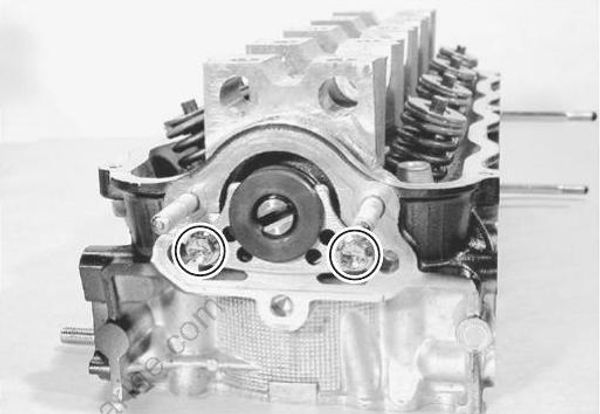
- Install the camshaft thrust plate by the two bolts.
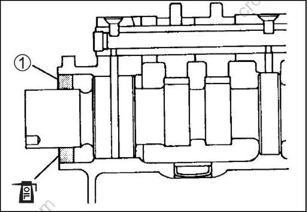
Apply the engine oil to the lip area of the oil seal (1).
Press fit the oil seal until its top face is lower than the block face by 0.5 mm.
Do not re-use the seal once removed. Always use a new seal.
- Make sure the camshaft smoothly rotates by hand.
ROCKER ARM/SHAFT
Apply the engine oil to the rocker arms and the rocker arm shafts.
Install the rocker arms, the rocker arm springs, the intake rocker arm shaft and the exhaust rocker arm shaft.
• Reassemble each rocker arm to its original position.
• The intake rocker arm shaft differs from the exhaust one in shape as shown. When assembling, make sure of shaft shape and installing direction.
- Tighten the ten screws.
Rocker arm shaft screw: 11 N·m (1.1 kg-m, 8.0 lb-ft)