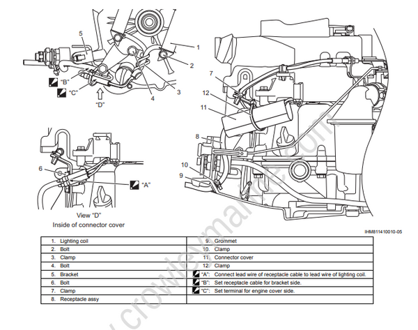
Schematic and Routing Diagram
Wiring Diagram
Refer to "Write color Symbols" in the Section 0A (Page 0A-2)
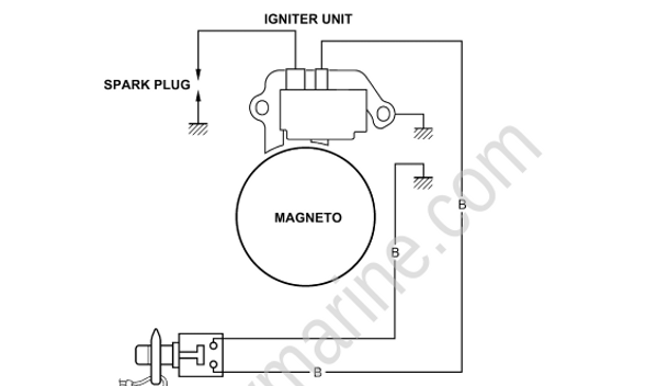
EMERGENCY & Stop Switch
EMERGENCY & Stop Switch: Lock plate IN→RUN
Lock plate OUT→STOP
EMERGENCY & Stop Switch: Button pushed→STOP
Optional parts
The flywheel must be changed from the standard one to the special (optional) one to generate electricity, in addition to the installation of the optional battery charge coil and related parts. The standard flywheel doesn't have the magnets for the electric power generation. The special (optional) flywheel equips the magnets for the electric power generation.
DC OUTPUT
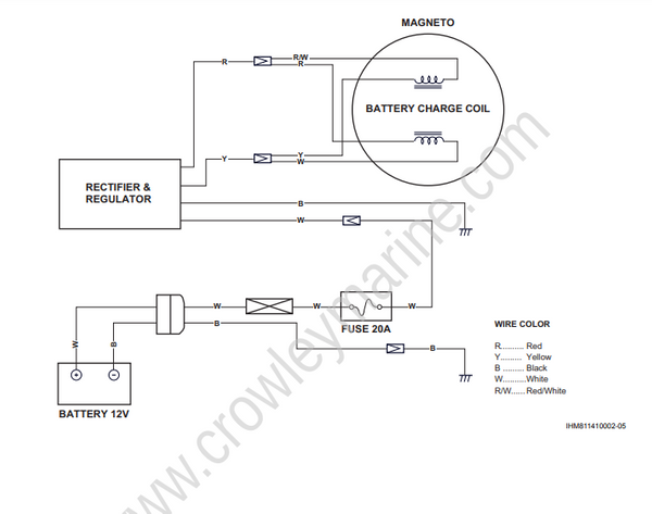
AC OUTPUT
Connecting a lower wattage lamp directly to the power receptacle of the motor could burn out or
damage the lamp.Do not connect a lower wattage lamp to the power receptacle of the motor
Connecting electrical accessories directly to the power receptacle of the motor can damage the accessories. Electrical accessories and lamps for the boat are recommended to be connected to the battery
Wiring Harness Routing Diagram
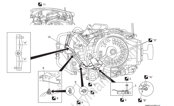
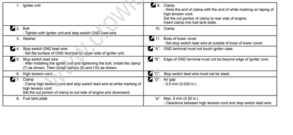
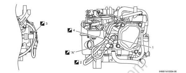

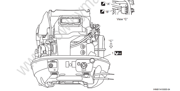

Optional Electrical Parts Installation
DC output
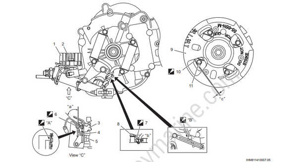
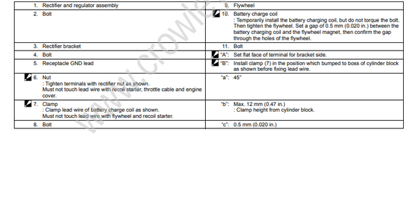
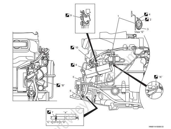
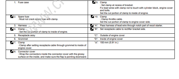
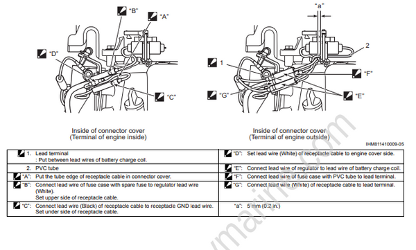
Install the terminal of engine inside, then install the terminal of engine outside.
AC output