

General Description
Fuel System Description
The main components of the fuel system are fuel tank, fuel filter, fuel pump, carburetor and fuel feed line.
A mechanical diaphragm type fuel pump on the motor draws fuel from the fuel tank through the fuel filter and supply it to the carburetor.
The flow of the fuel is shown in the figure.
Before the engine is started:
When the air vent on the fuel tank cap and the fuel cock are open, fuel is supplied to the carburetor through the fuel tank, fuel cock and check valve.
After the engine is started:
Fuel is supplied to the carburetor through the fuel tank and fuel cock, as well as the fuel filter and fuel pump.
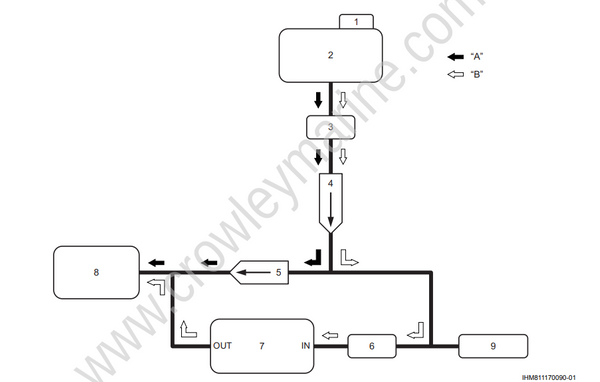
| 1. Fuel tank cap (with air vent) | 7. Fuel pump |
|---|---|
| 2. Fuel tank | 8. Carburetor |
| 3. Fuel cock | 9. Fuel connector (except for DF4A) |
| 4. Check valve (for US market) | “A": The flow of the fuel (Before the engine is started.) |
| 5. Check valve | "B": The flow of the fuel (After the engine is started.) |
| 6. Fuel filter |
Principles of Carburetor Operation Description
Float system
Fuel enter the carburetor from the fuel pump through the fuel inlet and float controlled needle valve into the float chamber.
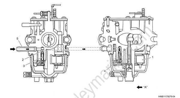
| 1. Float | 4. Float Pin |
|---|---|
| 2. Float valve seat | 5. Fuel inlet joint |
| 3. Float valve | “A": Fuel |
Idling / Trolling Speed
After passing through the pilotjet (1), fuel mixes with airthat is supplied from the pilot airjet (2).
This mixture then passes through the pilot screw (9) seating area and isjetted both from the pilot outlet (3) and bypass port #1 (5).
No mixture will be jetted either from the bypass port #2 (6) or from those located upstream but these ports serve as air passage.
As the pilot screw (9) is turned clockwise (screwed in), the mixture (A/F) will become leaner. As the screw is turned counterclockwise (screwed out), the mixture will become richer.
The throttle stop screw is designed to adjust the idling/trolling speed. When the stop screw is turned clockwise (screwed in), the speed raises and when turned counterclockwise (screwed out), the speed lowers.
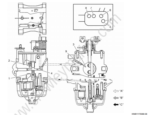
| 1. Pilot jet | 7. Bypass port #3 |
|---|---|
| 2. Pilot airjet | 8. Bypass port #4 |
| 3. Pilot outlet | 9. Pilot screw |
| 4. Bypass port | “A": AIR |
| 5. Bypass port #1 | ”B": FUEL + AlR (MIXTURE) |
| 6. Bypass port #2 | "C": FUEL |
Low-Mid Speed
As the throttle valve (10) is opened gradually, air flowing through the throttle bore increases in proportion to the valve opening angle. At this time, because fuel mixture jets from the bypass port #2 (6) and those upstream successively, the mixture ratio (A/F) is maintained to be optimum, thereby the engine speed being raised smoothly.
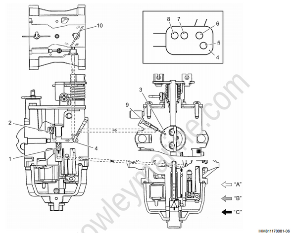
| 1. Pilot jet | 8. Bypass port #4 |
|---|---|
| 2. Pilot air jet | 9. Pilot screw |
| 3. Pilot outlet | 10. Throttle valve |
| 4. Bypass port | “A": AIR |
| 5. Bypass port #1 | “B": FUEL + AIR (MIXTURE) |
| 6. Bypass port #2 | "C": FUEL |
| 7. Bypass port #3 |
Mid-High Speed
When the throttle valve opens further and engine speed rises, fuel passes through the main jet (1) and enters the main nozzle (3), in which it is mixed with air supplied from the main airjet (2) before sprayed into the main bore.
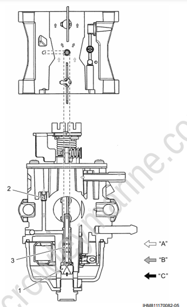
| 1. Main jet | “A": AIR |
|---|---|
| 2. Main airjet | “B": FUEL + AIR (MIXTURE) |
| 3. Main nozzle | “C": FUEL |
