OUTLINE
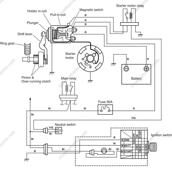
The starting circuit consists of the battery, starting motor, ignition switch, neutral switch and related electrical wiring.
These components are connected electrically as shown in figure below.
STARTING SYSTEM CIRCUIT
In the circuit shown in figure below, the magnetic switch coils are magnetized when the ignition switch is closed (turn to “START”).
The resulting plunger and pinion shift lever movement causes the pinion to engage the engine flywheel gear, the magnetic switch main contacts to close, and engine cranking to take place.
When the engine starts, the pinion over-running clutch protects the armature from excessive speed until the switch is opened, at which time the torsion spring causes the pinion to disengage
STARTER ENGAGEMENT MECHANISM
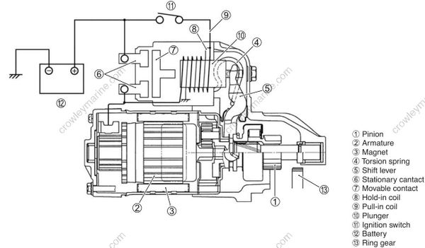
A solenoid (electromagnetic force) type starter switch, utilizing a torsion spring and shift lever, engages the pinion gear to the flywheel.
When the ignition key is turned to “START”, current flows through the switch winding creating an electromagnet pulling the plunger in.
The shift lever, attached to the plunger, then pushes the pinion up into engagement with the flywheel. Plunger and shift lever movement also compresses the torsion spring, which applies pressure against the shift lever and pinion gear to maintain positive engagement.
Final plunger movement closes the starter switch contacts, which allows current to flow through the starter motor windings, rotating the starter motor armature, pinion gear and flywheel.
When the ignition key is released from start, current flow to the switch is shut off and electromagnetic force ceases. The torsion spring then pulls the plunger out, disengaging the pinion gear from the flywheel through the shift lever.
Movement of the plunger also opens the switch contacts, stopping current flow to the starter motor windings,
shutting off the starter motor.
TROUBLESHOOTING
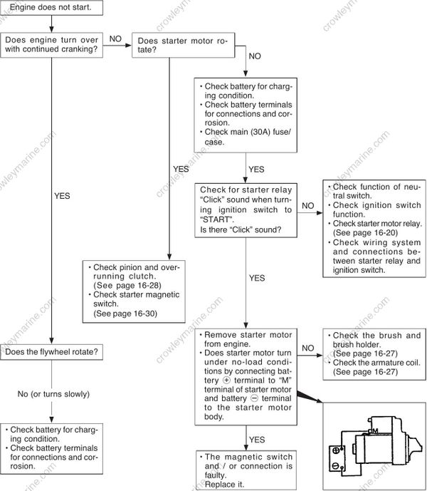
Before troubleshooting the electric starter system, make sure of the following:
• Battery is fully charged.
• All cables/wires are securely connected.
• Shift is in “NEUTRAL” position.
If any abnormality is found, immediately disconnect battery cables from battery
STARTER MOTOR RELAY
INSPECTION
TOOL09930-99320: Digital tester
Tester range: (Continuity)
(1) Disconnect relay from wire.
(2) Check continuity between terminal 1 and 2 each time 12 V is applied. Connect positive (+) side to terminal 4, and negative (–) side to terminal 3
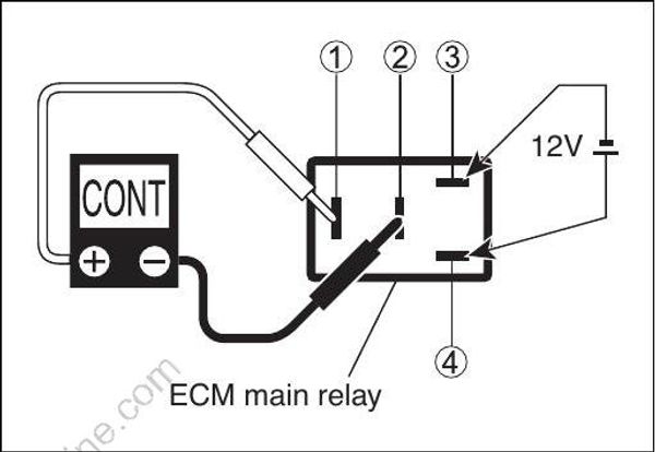
Relay function:
| 12 V power | Continuity |
|---|---|
| Applied | Yes |
| Not applied | No |
Be careful not to touch 12 V power supply wires to each other or with other terminals.
STARTER MOTOR
REMOVAL
Prior to removing Flywheel:
- Disconnect battery cables from battery.
- Remove three bolts, two fastening bands and flywheel cover.
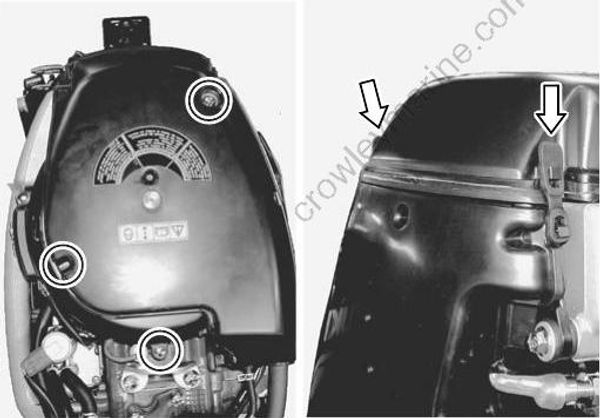
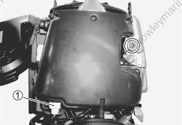
Remove a bolt and silencer cover.
Disconnect lead wire connector 1 from IAC sensor.
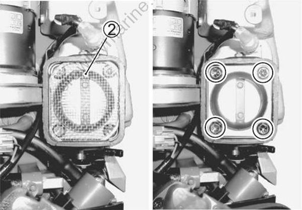
Remove flame arrester 2.
Remove four bolts, silencer plate and silencer seal.
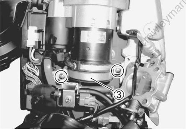
- Remove two bolts, negative (-) battery cable, ground lead wire and motor band (3).
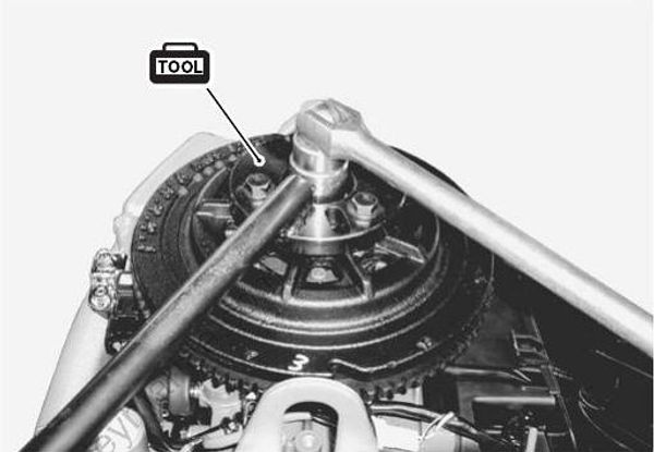
- Using special tool, loosen flywheel bolt 2 – 3 turns.
TOOL09930-48720: Flywheel holder
Do not remove flywheel bolt at this time.
This bolt prevents damage to the crankshaft when using flywheel remover tools.
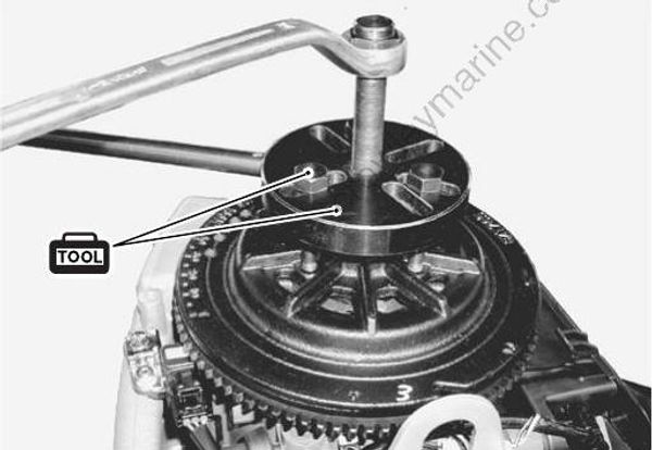
- Using special tools, loosen flywheel from crankshaft.
TOOL09930-39411: Flywheel remover
09930-39420: Flywheel remover bolt
- Remove flywheel bolt, washer and flywheel.
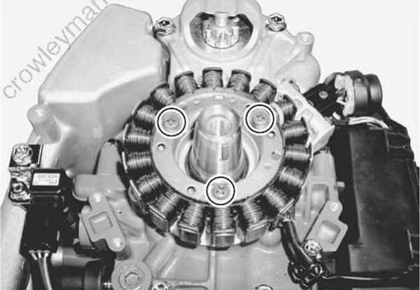
- Remove three screws and battery charge coil.
- Remove seven bolts, upper oil seal housing and starter motor.
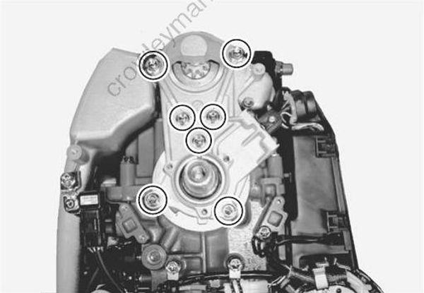
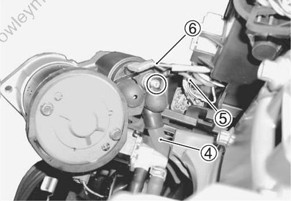
Remove nut, positive + battery cable 4 and Red lead wire 5.
Disconnect Red lead wire 6
INSTALLATION
Installation is reverse order of removal with special attention to the following steps.
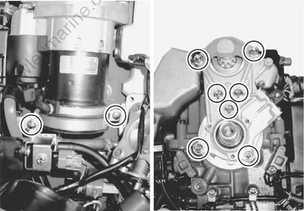
- Install starter motor and stator base, then tighten stator base mounting bolts securely.
Stator base mounting bolt:
8 mm 23 N·m (2.3 kg-m, 16.5 lb-ft)
6 mm 10 N·m (1.0 kg-m, 7.0 lb-ft)
DISASSEMBLY
When overhauling starting motor, it is recommended that component parts be cleaned thoroughly.
However, the yoke assembly, armature coil, over-running clutch assembly, magnetic switch assembly, and rubber or plastic parts should not be washed in a degreasing tank or with a grease dissolving solvent. These parts should be cleaned with compressed air or wiped with clean cloth.
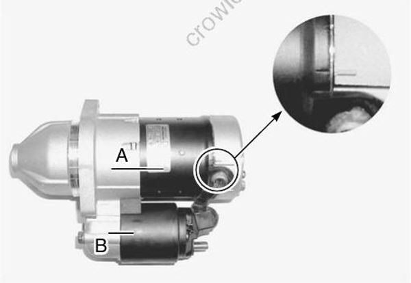
Before disassembling starting motor, be sure to put match marks at two locations (A and B) as shown in figure at right to avoid any possible component alignment mistakes.
Remove nut (1) from magnetic switch, then disconnect the connecting wire (2).
Remove two bolts (3) securing magnetic switch.
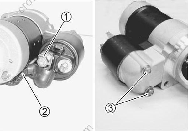
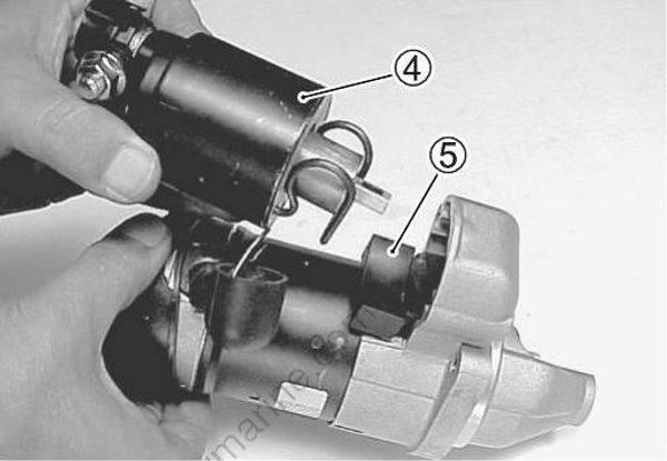
- Remove the magnetic switch (4) and rubber packing (5).
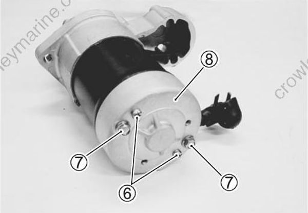
- Remove screws (6), long through bolts (7) and rear cover (8).
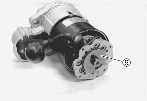
- Remove thrust washer (9) with screwdriver.
- Pull the brush spring (10) up to separate the brush from the surface of the commutator, then remove the brush holder (11).
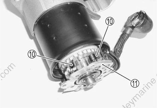
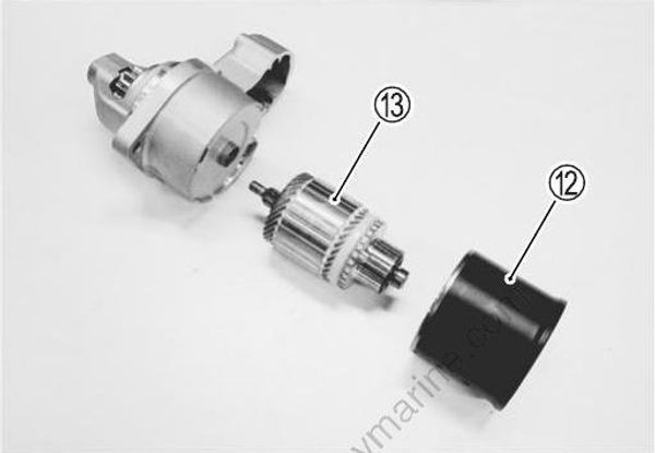
- Remove the yoke (12) and armature (13).
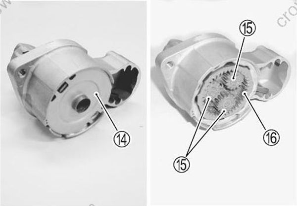
Remove the center cover plate (14).
Remove the planetary gears (15) and internal gear (16).
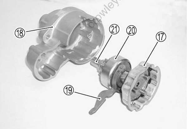
Remove the center bracket (17) (with shift lever (19), pinion (20) and pinion shaft (21) from front housing (18).
Remove the shift lever (19) from pinion (20).
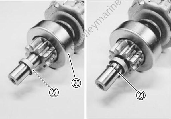
- Push the pinion stopper (22) down, then remove stopper ring (23).
Remove the pinion stopper and pinion (20).
Wear safety glasses when disassembling and assembling stopper ring
Using a screw-driver, pry off the stopper ring.
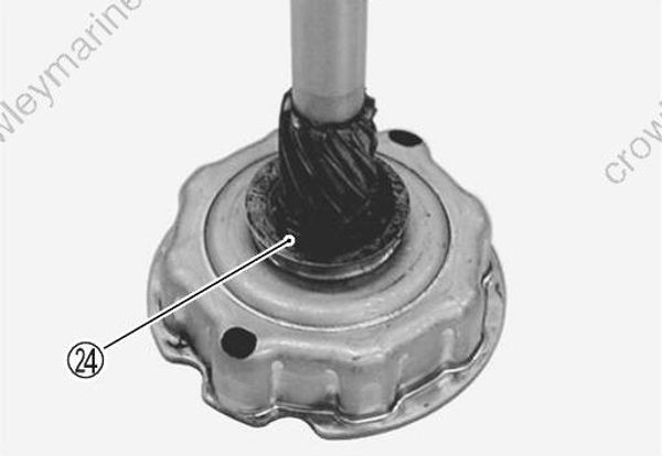
- Remove the E-ring (24).
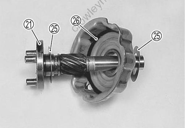
- Remove the pinion shaft (21), washers (25) and rubber ring (26) from center bracket.
INSPECTION AND SERVICING
Armature and Commutator
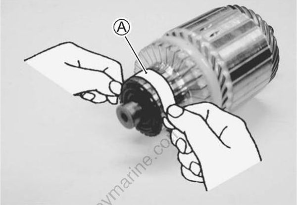
- Inspect the commutator surface.
If surface is gummy or dirty, clean with #500 grit emery paper (A).
- Measure commutator outside diameter.
TOOL09900-20101: Vernier calipers
Commutator outside diameter:
Standard: 29.0 mm (1.14 in)
Service limit: 28.0 mm (1.10 in)
If measurement exceeds service limit, replace armature.
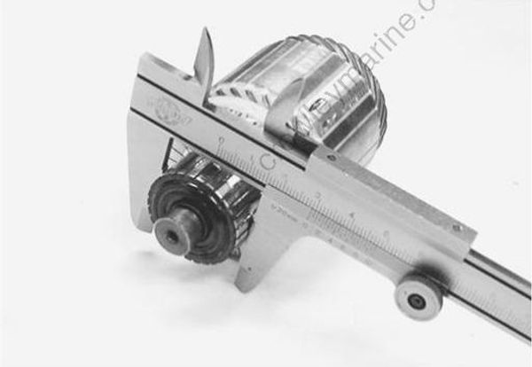
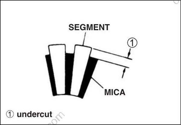
- Check that mica (insulator) between the segments is undercut to specified depth.
Commutator undercut (1):
Standard: 0.5 – 0.8 mm (0.02 – 0.03 in)
Service limit: 0.2 mm (0.01 in)
If measurement exceeds service limit, cut to specified depth.
Remove all particles of mica and metal using compressed air.
Wear safety glasses when using compressed air.
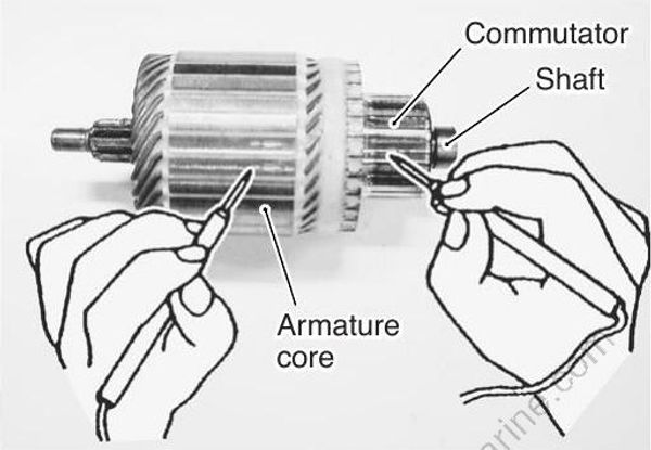
- Check for continuity between the commutator and the armature core/shaft.
Replace armature if continuity is indicated.
TOOL09930-99320: Digital tester
Tester range: (Continuity)
- Check for continuity between adjacent commutator segments.
Replace armature if no continuity is indicated.
TOOL09930-99320: Digital tester
Tester range: (Continuity)
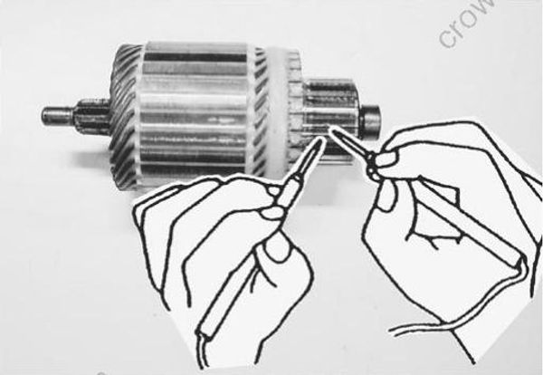
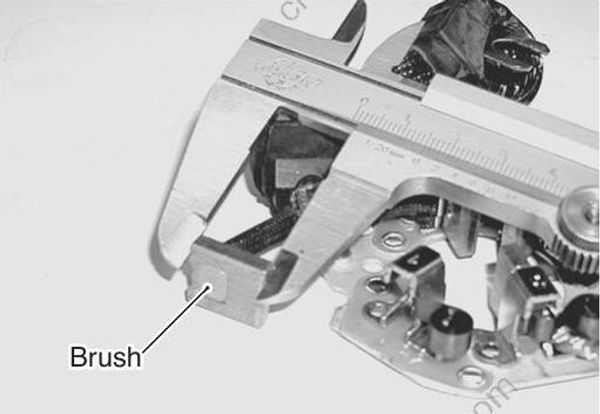
BRUSHES
Check the length of each brush.
TOOL09900-20101: Vernier calipers
Brush length:
Standard: 15.5 mm (0.61 in)
Service limit: 9.5 mm (0.37 in)
If brushes are worn down to the service limit, they must be replaced.
BRUSH HOLDER
- Check brush holder continuity.
TOOL09930-99320: Digital tester
Tester range: (Continuity
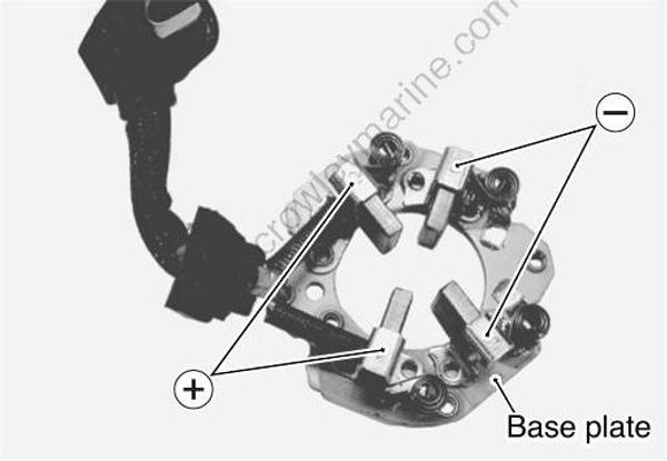
| Tester probe connection | Continuity |
|---|---|
| Brush holder positive + to Brush holder negative - | No |
| Brush holder positive + to Base plate (ground) | No |
Replace brush holder if the tester doesn’t show the above.
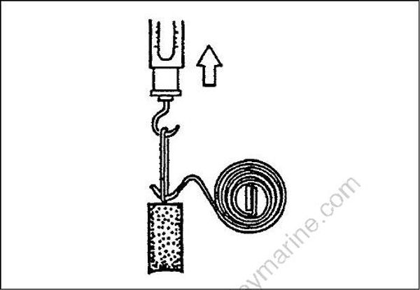
BRUSH SPRING
Inspect brush spring for wear, damage or other abnormal conditions.
Check the brush spring tension.
Replace if necessary.
Brush spring tension
Standard: 15 – 18 N (1.5 – 1.8 kg, 3.3 – 4.0 lb)
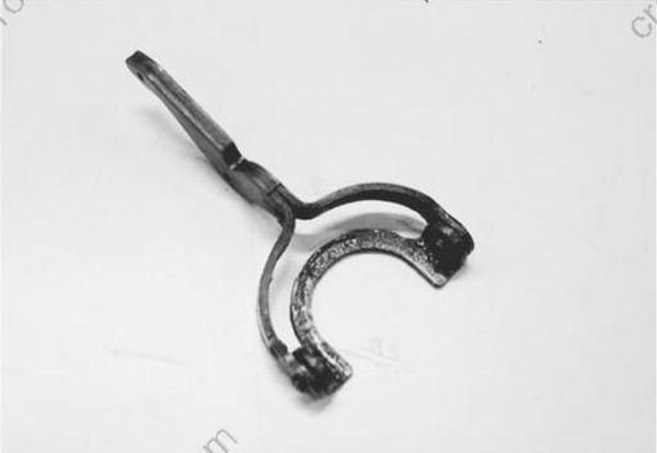
SHIFT LEVER
Inspect shift lever for wear.
Replace if necessary
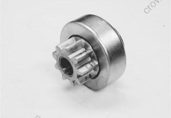
PINION AND OVER-RUNNING CLUTCH
- Inspect pinion for wear, damage or other abnormal conditions.
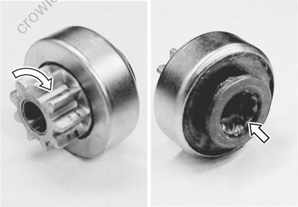
Check that clutch locks up when turned in direction of drive and rotates smoothly in reverse direction.
Replace if necessary
- Inspect spline teeth for wear or other damage.
Inspect pinion for smooth movement.
Replace if necessary.
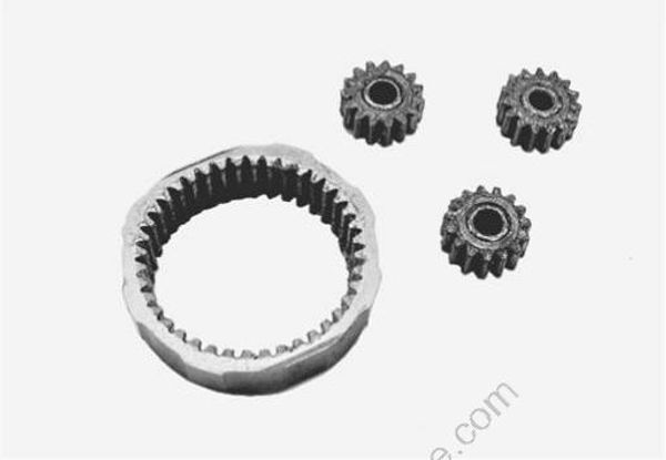
GEAR
- Inspect planetary gears and internal gear for wear, damage or other abnormal conditions.
Replace if necessary.
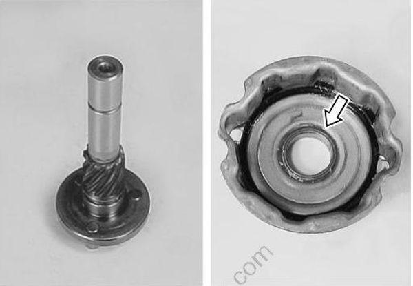
PINION SHAFT/PINION SHAFT BUSH
- Inspect pinion shaft for wear, damage or other abnormal conditions. Replace if necessary.
- Inspect pinion shaft bush for wear or other damage.
Replace if necessary.
FRONT HOUSING
- Inspect front housing for wear, damage or other abnormal conditions. Replace if necessary.
- Inspect bush for wear or other damage.
Replace if necessary.
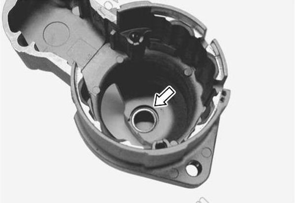
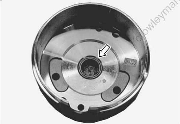
ARMATURE SHAFT BUSH
Inspect bush for wear or other damage.
Replace if necessary
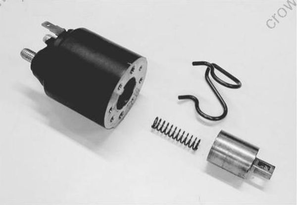
PLUNGER
Inspect plunger for wear or other damage.
Replace if necessary
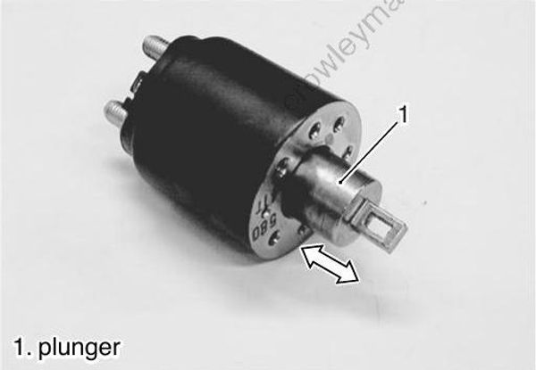
MAGNETIC SWITCH
Push in plunger and release. The plunger should return quickly to its original position.
Replace if necessary
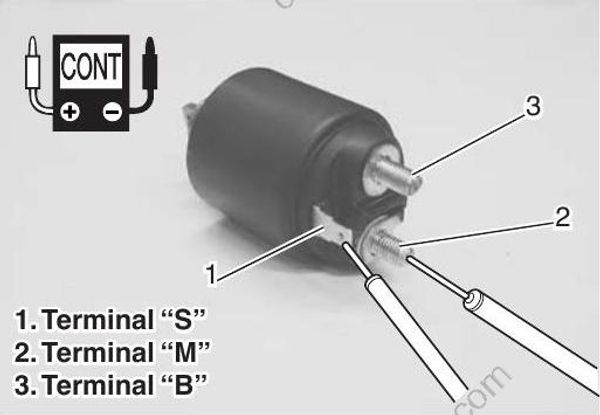
Pull-in coil Open circuit Test
TOOL09930-99320: Digital tester
Tester range: (Continuity)
Check for continuity across magnetic switch “S” terminal and “M” terminal.
If no continuity exists, the coil is open and should be replaced.
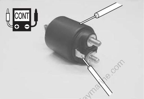
Hold-in coil Open circuit Test
TOOL09930-99320: Digital tester
Tester range: (Continuity)
Check for continuity across magnetic switch “S” terminal and coil case.
If no continuity exists, the coil is open and should be replaced.
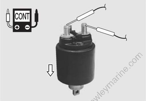
Contact points Test
TOOL09930-99320: Digital tester
Tester range: (Continuity)
Put the plunger on the under side and then push the magnetic switch down. At this time, check for continuity between terminal “B” and terminal “M”.
Continuity indicates proper condition. If no continuity exists, replace the magnetic switch and/or plunger.