

Starting System
General Description
Electric Starter System Description
The starting circuit consists of the battery, starter motor, main switch, “START & STOP” switch, neutral switch, BCM, ECM and related electrical wiring.
These components are connected electrically as shown in figure below.
In the circuit shown in figure below, the magnetic switch coils are magnetized when the main switch is closed (turn to “ON”) and depress the “START & STOP” button.
The resulting plunger and pinion shift lever movement causes the pinion to engage the engine flywheel gear, the magnetic switch main contacts to close, and engine cranking to take place.
When the engine starts, the pinion over-running clutch protects the armature from excessive speed until the switch is opened, at which time the torsion spring causes the pinion to disengage.
Normal key start model
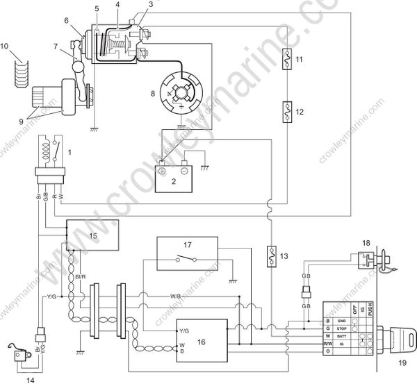
- Starter relay
- Battery
- Magnetic switch
- Pull-in coil
- Hold-in coil
- Plunger
- Shift lever
- Starter motor
- Pinion/over-running clutch
- Ring gear
- 60 A fuse
- Starter relay 30 A fuse
- 30 A fuse
- Neutral switch
- ECM
- BCM
- START & STOP switch
- Emergency stop switch
- Main switch
Keyless start model
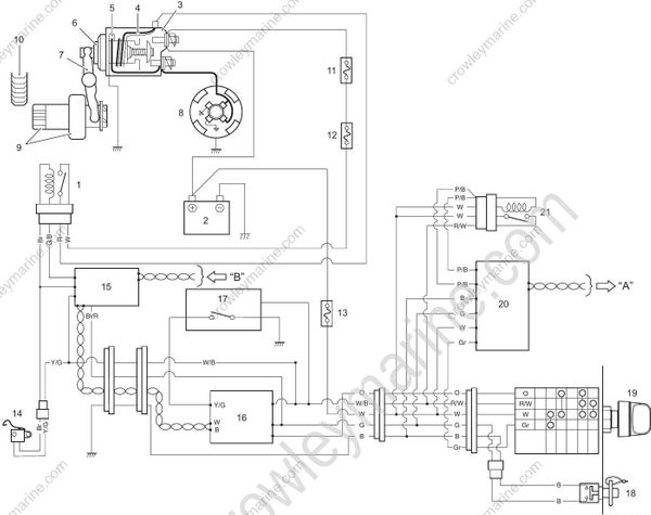
- Starter relay
- Battery
- Magnetic switch
- Pull-in coil
- Hold-in coil
- Plunger
- Shift lever
- Starter motor
- Pinion/over-running clutch
- Ring gear
- 60 A fuse
- Starter relay 30 A fuse
- 30 A fuse
- Neutral switch
- ECM
- BCM
- START & STOP switch
- Emergency stop switch
- Main switch
- Keyless control unit
- ECM power relay
“A”: to ECM
“B”: from keyless control unit
Starter Motor Operation Condition Description
- The starter motor relay will only engage when the main switch is turned to “ON” position and depress the “START & STOP” button if the all of the following conditions are satisfied.
- Lock plate is attached to emergency stop switch.
- Neutral switch is in “ON” position.
- Engine is not already operating.
- When BCM detects that the target shift position is neutral according to the LPS input signal.
- When BCM detects that the actual shift position is neutral according to the SPS (ECM) input signal.
- Push the “START & STOP” switch and release it, the starter motor continues to run for 3 seconds until engine starts.
The continuous operating time of the starter motor is set at five seconds. When this time is exceeded, the starter motor will automatically stop. If the motor stops, wait about ten seconds for the motor to cool down and try again.
Start-In-Gear Protection System Description
To avoid an accidental movement of the boat at the time of engine starting, the system prohibits the starter motor operation when the shift is “IN”.
At the time of starting, BCM detects the status of each input signal.
When the conditions below are met, pressing “START & STOP” switch causes the start instruction signal to be sent to ECM. Then the starter relay circuit is closed and the starter motor starts to operate.
- When BCM detects that the target shift position is neutral according to the LPS input signal.
- When BCM detects that the actual shift position is neutral according to the SPS (ECM) input signal.
- When ECM and BCM detects emergency stop switch OFF signal.
If “START & STOP” switch is pressed and the start instruction signal from BCM is not inputted to ECM, the starter motor does not operate and ECM does not output the injection drive signal, ignition signal, high pressure fuel pump drive signal to the respective actuators.
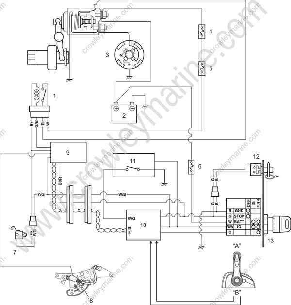
- Starter relay
- Battery
- Starter motor
- 60 A fuse
- Starter relay 30 A fuse
- 30 A fuse
- Neutral switch
- Shift position sensor
- ECM
- BCM
- START & STOP switch
- Emergency stop switch
- Main switch
“A”: Neutral
“B”: LPS signal
The illustration below is for the regular rotation. When changing regular rotation to counter one, forward position and reverse one become opposite.
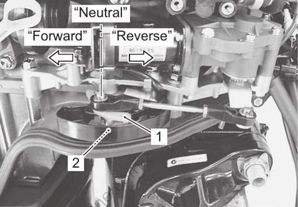
- Clutch lever
- Neutral switch
Component Location
Starting System Components Location
Refer to “Wiring Harness Routing Diagram” in Section 4A (Page 4A-4).
Diagnostic Information and Procedures
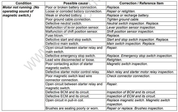
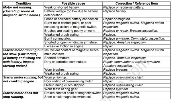
Starter System Troubleshooting
Failure to take proper precaution when starter system troubleshooting may result in personal injury and/or damage to electronic components.
If any abnormality is found, immediately disconnect the battery cables from the battery.
Before troubleshooting the electric starter system, make sure of the following:
• Battery is fully charged.
• All cables/wires are securely connected.
• Shift is in neutral position.
• Emergency stop switch lock plate is set in place.
• Fuse is not blown.
Service Instructions
Starter Motor Removal and Installation
Removal
If the 12 V electrical system is shorted while servicing the starter motor, the engine electrical circuits could be damaged seriously.
Prior to removing starter motor, disconnect the battery cable at the battery.
Remove ring gear cover.
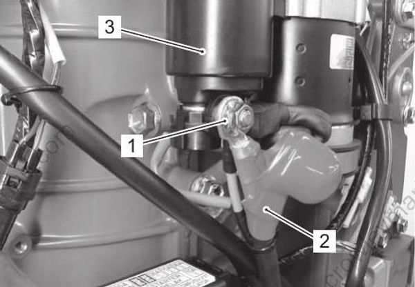
Refer to “Ring Gear Cover Removal and Installation” in Section 1D (Page 1D-2).Remove the nut (1) securing positive (+) battery cable (2) and main harness (R) lead wire from magnetic switch (3) of starter motor.
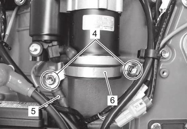
- Remove two bolts (4), negative (-) battery cable (5), harness GND lead wire and starter motor band (6).
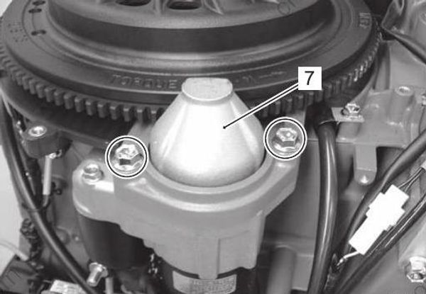
- Remove two bolts securing starter motor (7).
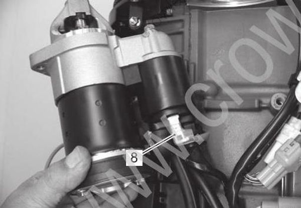
- Remove the starter motor, then disconnect the red lead wire (8) from “S” terminal of starter motor magnetic switch.
Installation
Installation is reverse order of removal with special attention to the following steps.
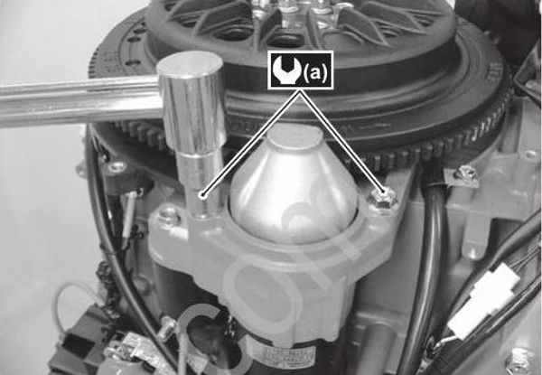
- Install starter motor and tighten starter motor mounting bolts securely.
Tightening torque
Starter motor mounting bolt (a): 23 N•m (2.3 kgf•m, 16.5 lbf•ft)
Starter Motor Test
Sparks resulting from short circuit between the positive (+) and negative () terminals during connections to the battery could cause a burn.
Be careful not to short-circuit the positive (+) and negative () cables and connect them only to the correct terminals.
If the cable used for the test is not adequately thick, the cable may become extremely hot due to large current flowing through it and you could get burned.
Be sure to connect the battery and the starting motor with a lead wire of the same size as original equipment.
If battery power is applied too long in any of the following tests, the coil of the magnetic switch may burn.
Each test must be completed within 3 5 seconds to avoid burning of the coil.
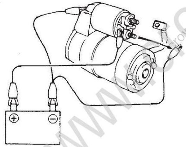
Pull-In / Hold-In Test
Before testing, disconnect the brush lead from terminal “M”.
Connect the battery to the magnetic switch as shown in the figure.
- Check that the plunger and pinion (over-running clutch) move outward.
If the plunger and pinion don’t move, replace the magnetic switch.
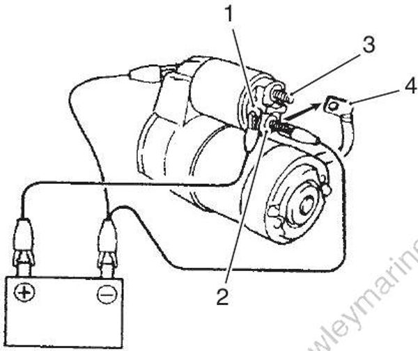
1.Terminal “S”
2.Terminal “M”
3.Terminal “B”
4.Brush lead
- While connected as above with the plunger out, disconnect the negative lead from terminal “M”.
Check that the plunger and pinion remain out. If the plunger and pinion return inward, replace the magnetic switch.
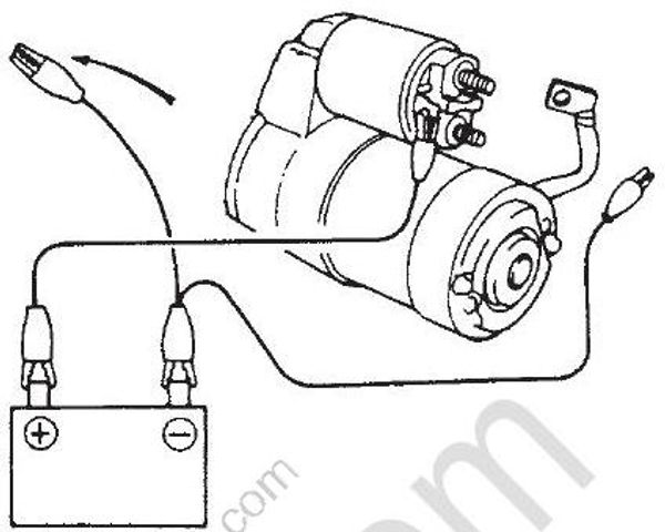
Plunger and Pinion Return Test
Disconnect the negative lead from the switch/motor body.
Check that the plunger and pinion return inward.
If the plunger and pinion don't return inward, replace the magnetic switch.
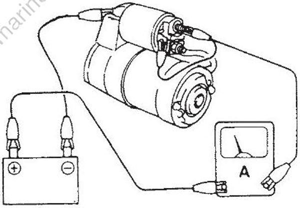
No-Load Performance Test
Before performing the following test, secure the starter motor to the test bench.
Connect a battery and ammeter to the starter motor as shown.
Check that the starter rotates smoothly and steadily with the pinion moving out. Check that the ammeter indicates the specified current.
Specified current (No-load performance test)
Within 90 A at 11 V
Starter Motor Components
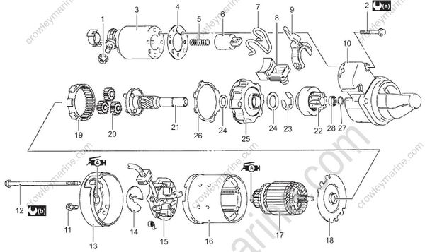

Starter Motor Disassembly and Assembly
Disassembly
When overhauling the starting motor, it is recommended that the component parts be cleaned thoroughly. However, the yoke assembly, armature coil, over-running clutch assembly, magnetic switch assembly and rubber or plastic parts should not be washed in a degreasing tank or with a grease dissolving solvent.
These parts should be cleaned with compressed air or wiped with clean cloth.
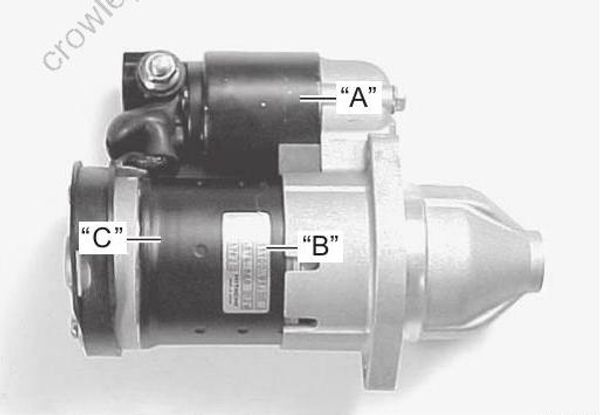
Before disassembling the starting motor, be sure to put match marks at three locations (“A”, “B” and “C”) as shown in the figure at right to avoid any possible component alignment mistakes.
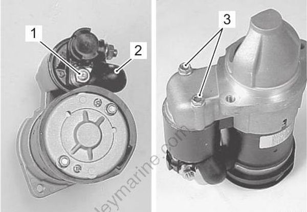
Remove nut (1) from the magnetic switch, then disconnect the connecting wire (2).
Remove two bolts (3) securing the magnetic switch.
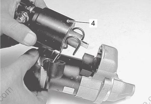
- Remove the magnetic switch (4).
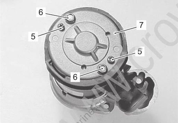
- Remove screws (5), long through bolts (6) and the rear cover (7).
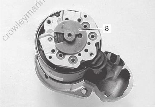
- Remove thrust washer (8) with a screwdriver.
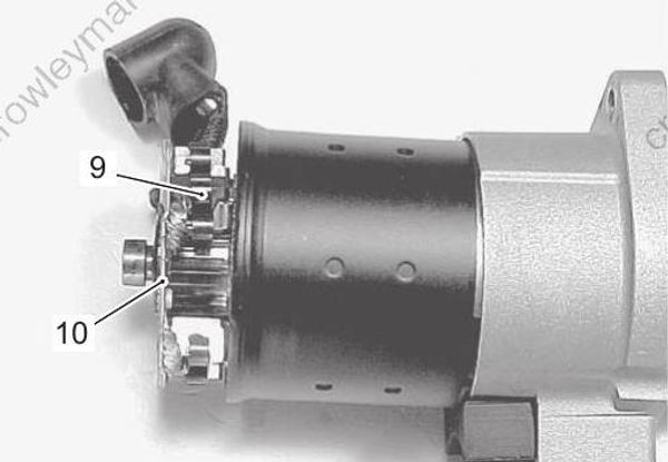
- Pull the brush spring (9) up to separate the brush from the surface of the commutator, then remove the brush holder (10).
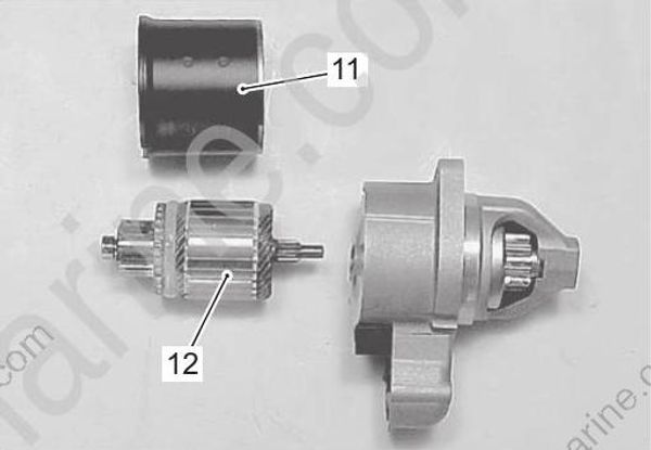
- Remove the yoke (11) and armature (12).
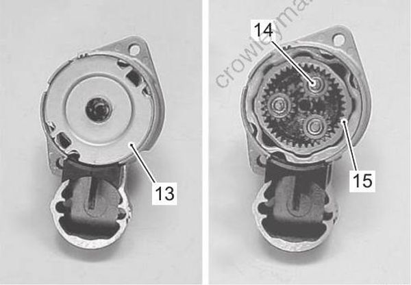
Remove the center cover plate (13).
Remove the planetary gears (14) and internal gear (15).
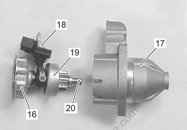
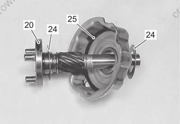
- Remove the center bracket (16) (with shift lever (18), pinion (19) and pinion shaft (20)) from front housing (17).
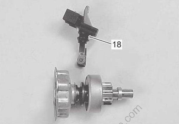
- Remove the shift lever (18).
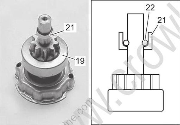
- Push the pinion stopper (21) down, then remove stopper ring (22).
Remove the pinion stopper and pinion (19).
Failure to take proper precautions when removing stopper ring can cause personal injury.
Wear safety glasses when disassembling and assembling the stopper ring.
Using a screw-driver, pry off the stopper ring.
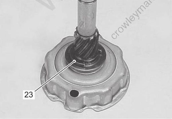
- Remove the E-ring (23).
- Remove the pinion shaft (20), washers (24) and rubber ring (25) from the center bracket.
Assembly
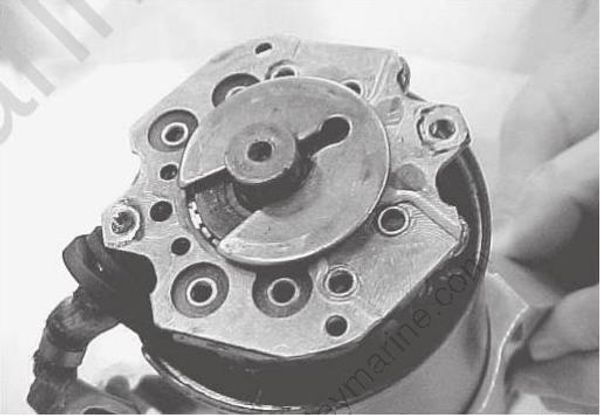
Assembly is in the reverse order of disassembly with special attention to the following steps.
Reassemble the starter motor, refer to “Starter Motor Components” (Page 1I-9).
- When installing the armature, use care to avoid breaking the brushes.
Starter Motor Components Inspection and Servicing
Armature and Commutator
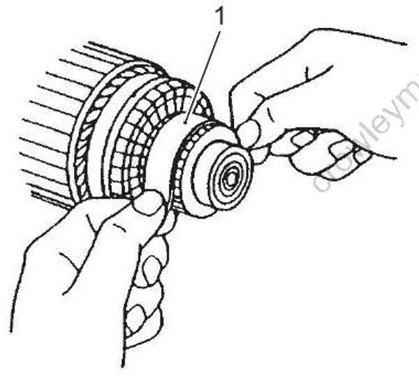
- Inspect the commutator surface. If surface is gummy or dirty, clean with 500 grit emery paper (1).
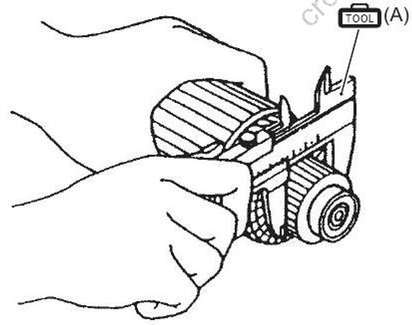
- Measure the commutator outside diameter. If the measurement exceeds the service limit, replace the armature.
Special tool
(A): 0990020101 (Vernier calipers (150 mm))
Commutator outside diameter
Standard: 29.0 mm (1.14 in.)
Service limit: 28.0 mm (1.10 in.)
Check that the mica (insulator) (2) between the segments (3) is undercut to specified depth “a”.
If the measurement exceeds the service limit, cut to the specified depth.Failure to following proper precautions during use of the compressed air may cause severe personal injury.
Wear safety glasses when using compressed air.
Remove all particles of mica and metal using compressed air.
Commutator undercut “a”
Standard: 0.5 0.8 mm (0.02 0.03 in.)
Service limit: 0.2 mm (0.01 in.)
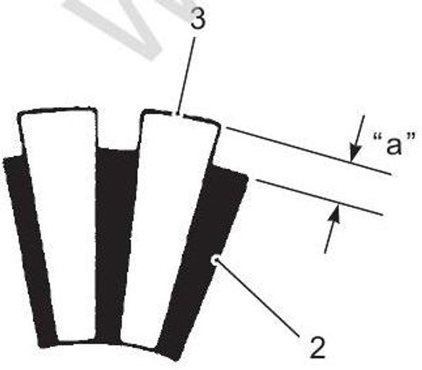
2. Mica
3. Segment
- Check for continuity between the commutator (4) and the armature core (5)/shaft (6).
Replace the armature if continuity is indicated.
Special tool
(B): 0990025008 (Multi circuit tester set)
Tester knob indication
Continuity ( )
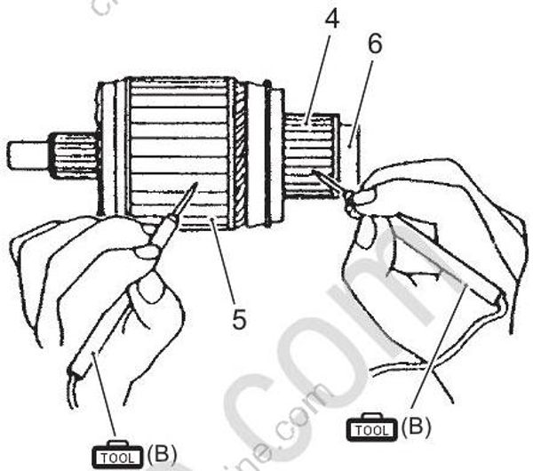
4. Commutator
5. Armature core
6. Shaft
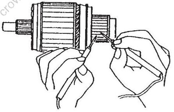
- Check for continuity between adjacent commutator segments. Replace armature if no continuity is indicated.
Tester knob indication
Continuity ( )
Brushes
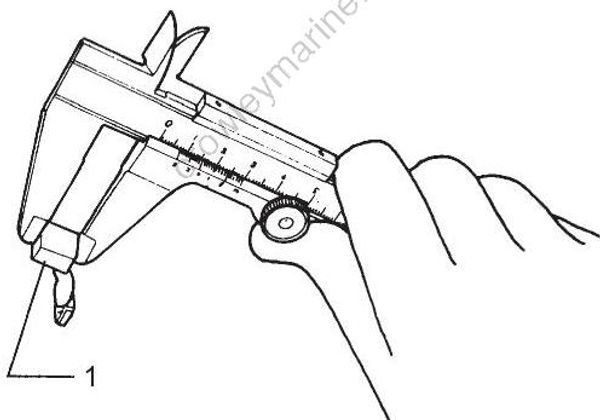
Check the length of each brush (1).
If brushes are worn down to the service limit, they must be replaced.
Special tool
(A): 0990020101 (Vernier calipers (150 mm))
Brush length
Standard: 16.0 mm (0.63 in.)
Service limit: 12.0 mm (0.47 in.)
Brush Holder
Check brush holder continuity.
Replace the brush holder if the tester doesn't show the below.
Special tool :
0990025008 (Multi circuit tester set)
Tester knob indication
continuity ( )
Brush holder continuity
| Continuity | |
|---|---|
| Brush holder positive (+) to brush holder negative (-) | No |
| Brush holder positive (+) to base plate (ground) | No |
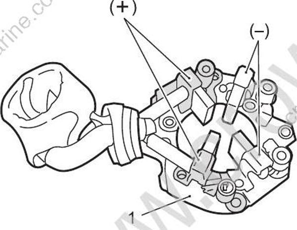
- Base plate
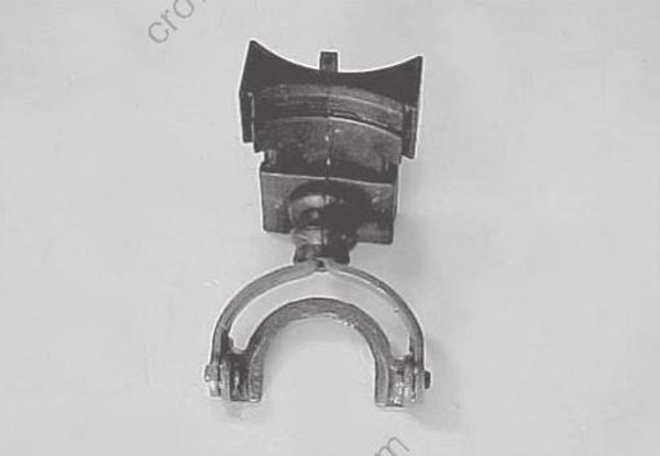
Shift Lever
Inspect the shift lever for wear. Replace if necessary.
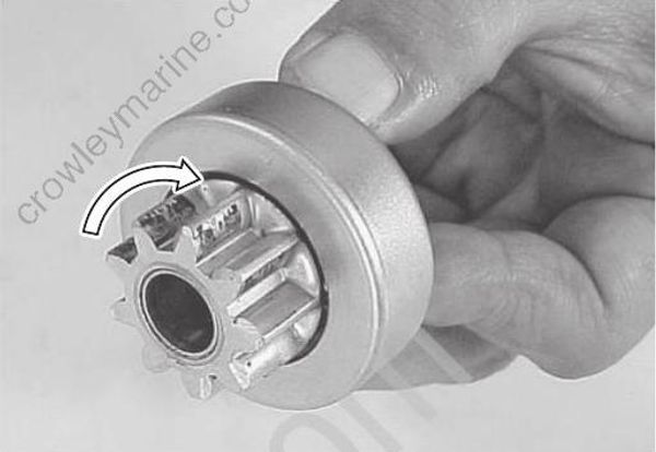
Pinion and Over-Running Clutch
- Inspect the pinion for wear, damage or other abnormal conditions.
Check that the clutch locks up when turned in the direction of drive and rotates smoothly in reverse direction. Replace if necessary.
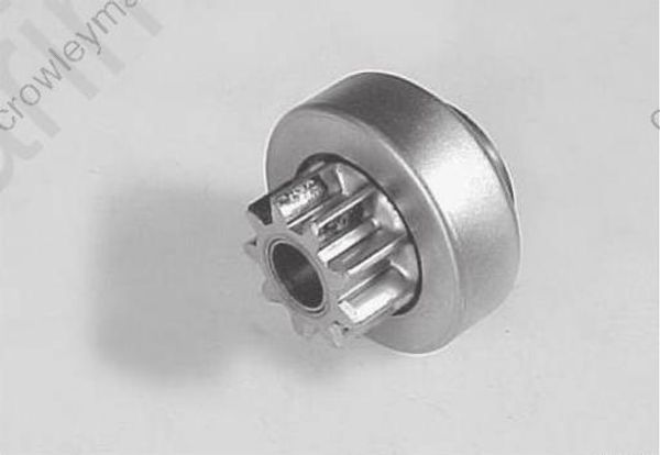
- Inspect spline teeth for wear or other damage.
Inspect the pinion for smooth movement. Replace if necessary.
Gear
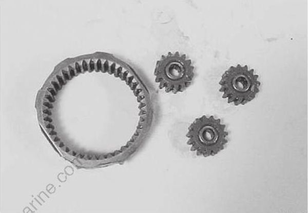
Inspect planetary gears and internal gear for wear, damage or other abnormal conditions. Replace if necessary.
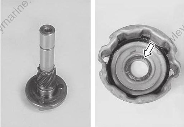
Pinion Shaft / Pinion Shaft Bushing
Inspect the pinion shaft for wear, damage or other abnormal conditions. Replace if necessary.
Inspect the pinion shaft bushing for wear or other damage.
Replace if necessary.
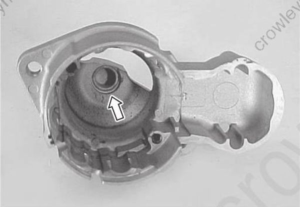
Front Housing
Inspect the front housing for wear, damage or other abnormal conditions. Replace if necessary.
Inspect the bushing for wear or other damage. Replace if necessary.
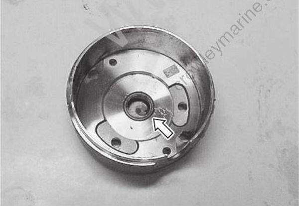
Armature Shaft Bush
Inspect the bushing for wear or other damage. Replace if necessary.
Plunger
Inspect the plunger for wear or other damage. Replace if necessary.
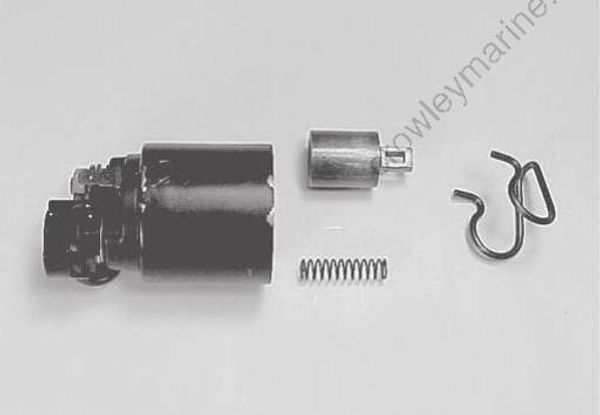
Magnetic Switch
Push in the plunger and release. The plunger should return quickly to its original position. Replace if necessary.
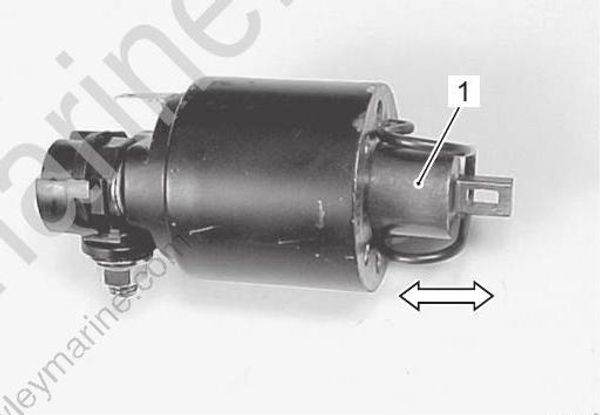
- Plunger
Pull-in coil open circuit test
Check for continuity across the magnetic switch terminal “S” (1) and terminal “M” (2).
If no continuity exists, the coil is open and should be replaced.
Special tool
(A): 0990025008 (Multi circuit tester set)
Tester knob indication
continuity ( )
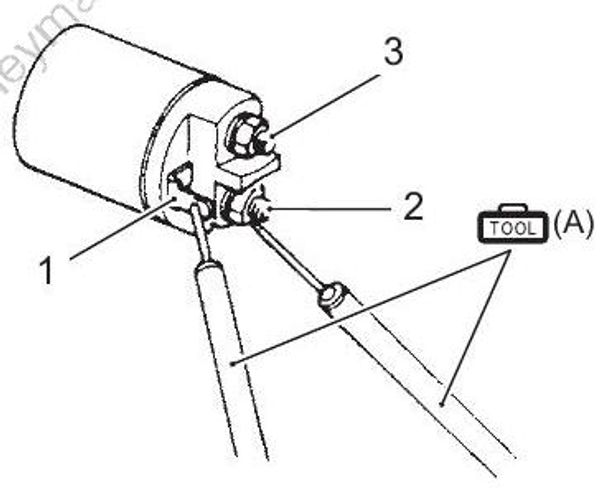
- Terminal “S”
- Terminal “M”
- Terminal “B”
Hold-in coil open circuit test
Check for continuity across the magnetic switch terminal “S” (1) and coil case (4).
If no continuity exists, the coil is open and should be replaced.
Special tool
(A): 09900–25008 (Multi circuit tester set)
Tester knob indication
Continuity ( )
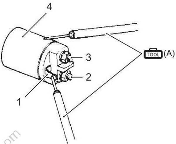
1.Terminal “S”
2.Terminal “M”
3.Terminal “B”
4.Coil case
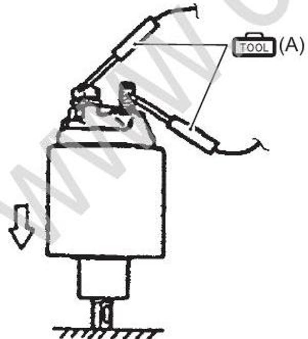
Contact points test
Put the plunger on the under side and then push the magnetic switch down.
At this time, check for continuity between terminal “B” and terminal “M”.
Continuity indicates proper condition. If no continuity exists, replace the magnetic switch and/or plunger.
Special tool
(A): 0990025008 (Multi circuit tester set)
Tester knob indication
Continuity ( )
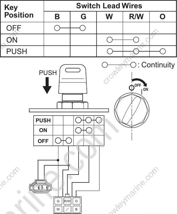
Main Switch Inspection
Inspect main switch using following procedures:
Disconnect the main switch from switch panel wiring harness.
Check continuity between wiring leads at the key positions shown in the chart.
If out of specification, replace main switch.
Normal key start model
Keyless start model
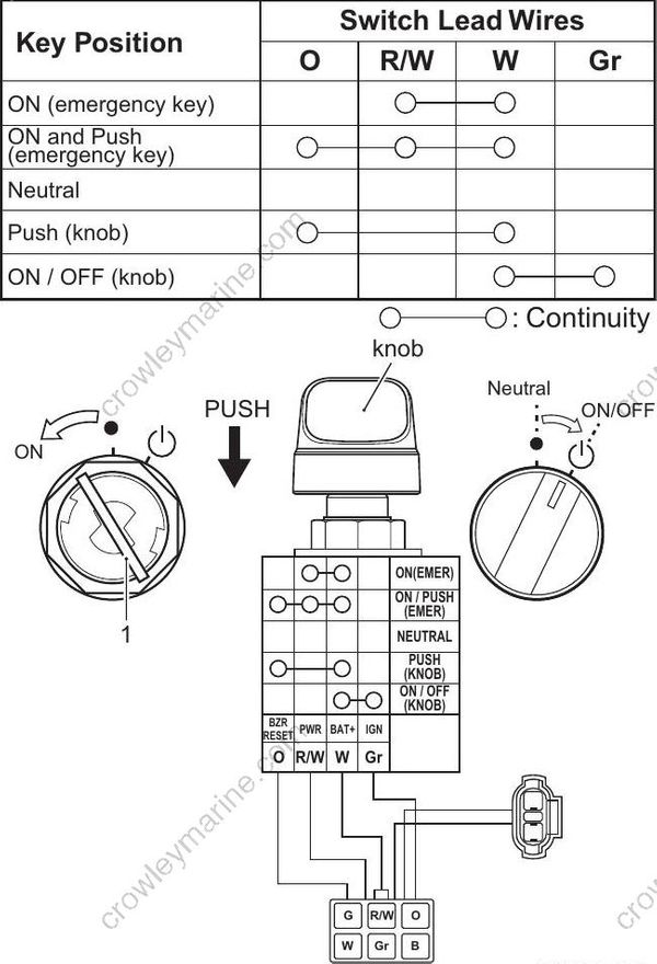
- Emergency key
Starter Motor Relay Inspection
Inspect the starter motor relay using the following procedures:
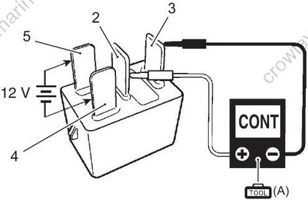
- Disconnect the starter motor relay (1) from the fuse box.
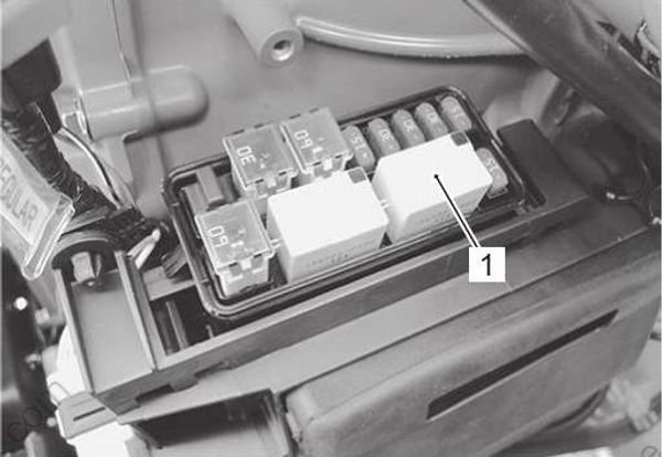
- Starter motor relay
- Check continuity between terminal (2) and (3) each time 12 V power supply is applied to terminal (4) and (5).
Connect the positive (+) lead to terminal (5), and negative () lead to terminal (4).
If the 12 V power supply wire is connected to wrong terminal or touched to each other, the power supply wire, tester may be damaged.
Be careful not to touch 12 V power supply wires to each other or with other terminals.
Special tool
(A): 0990025008 (Multi circuit tester set)
Tester knob indication
Continuity ( )
Starter motor relay function
| Continuity | |
|---|---|
| 12 V power applied | Yes |
| 12 V power not applied | No |
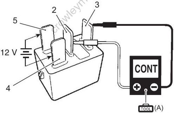
Measure the resistance between relay terminals (4) and (5).
If out of specification, replace starter motor relay.Tester knob indication
Resistance (Ω)
Starter motor relay solenoid coil resistance
Standard: 145 190 Ω
Neutral Switch Removal and Installation
Removal
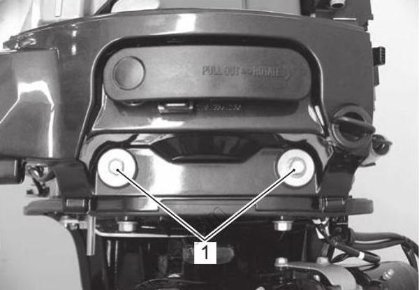
Turn the main switch “OFF”.
Remove lower side covers.
Refer to “Lower Side Cover Removal and Installation” in Section 2A (Page 2A-3).Remove two bolts (1) securing front panel.
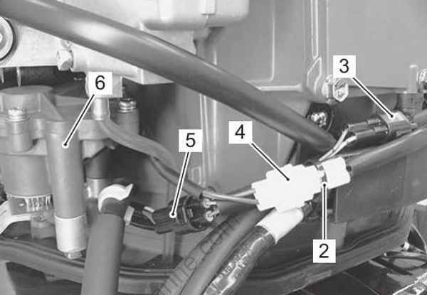
Remove the clamp (2).
Disconnect neutral switch lead wire connector (3), ESA lead wire connector (4) and shift position sensor lead wire connector (5).Remove ESA (6).
Refer to “ESA (Electronic Shift Actuator) and Shift Position Sensor Removal and Installation” in Section 1C (Page 1C-22).
- Remove the E-ring (7).
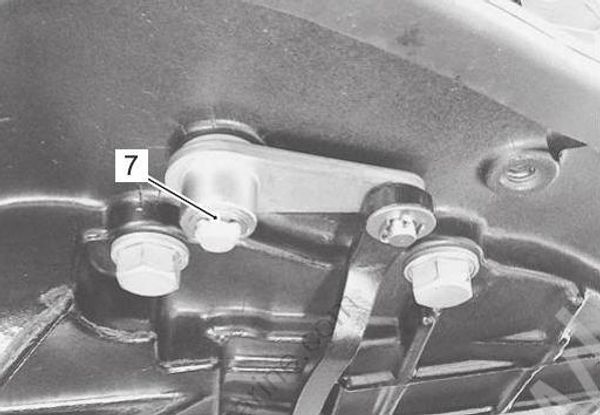
- Remove the two bolts securing clutch holder (8). Remove the clutch holder with neutral switch and shift position sensor.
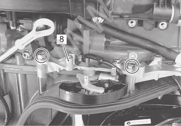
- Remove the clamp (9).
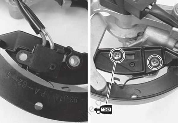
Remove two screws securing neutral switch cover (10).
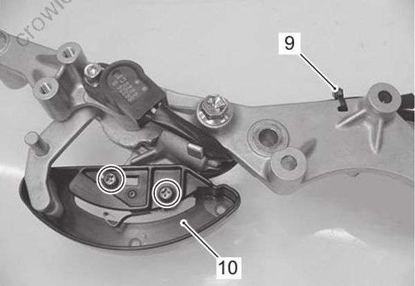
- Remove neutral switch (11) from the cover.
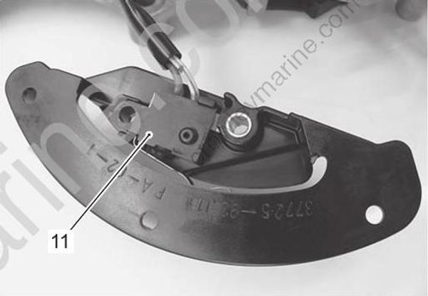
Installation
Installation is reverse order of removal with special attention to the following steps.
- Install the switch into position.
- Tighten the switch mounting screws, precoated with thread lock.
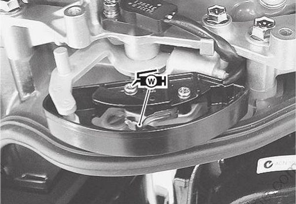
Check wiring harness routing.
Refer to “Wiring Harness Routing Diagram” in Section 4A (Page 4A-4).Apply water resistant grease to the switch lever.
Grease 9900025350 (SUZUKI Water Resistant Grease EP2 (250 g))
Install ESA.
Refer to “ESA (Electronic Shift Actuator) and Shift
Position Sensor Removal and Installation” in Section 1C (Page 1C-22).Install lower side covers.
Refer to “Lower Side Cover Removal and Installation” in Section 2A (Page 2A-3).
Neutral Switch Inspection
Check for continuity/infinity of the neutral switch.
Turn the main switch “OFF”.
Remove lower side covers.
Refer to “Lower Side Cover Removal and Installation” in Section 2A (Page 2A-3).Make sure that clutch lever is in “NEUTRAL”.
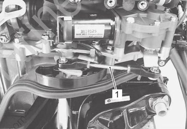
Remove the clip, washer and clutch link rod (1) from clutch lever.
Removing the shift link rod in an inappropriate procedure can result the electric shift system failure. Remove the main relay or shift actuator fuse from fuse box before removing clutch link rod to avoid shift actuator damage.
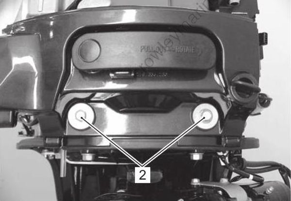
- Remove two bolts (2) securing front panel.
- Disconnect the neutral switch lead wire connector (3).
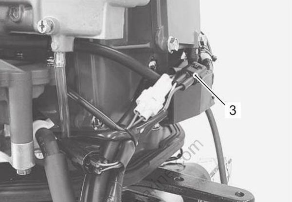
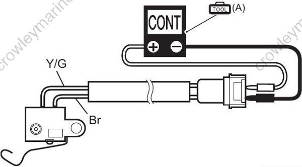
- Check continuity/infinity between the Y/G and Br lead wires while operating clutch lever (4).
Special tool
(A): 0990025008 (Multi circuit tester set)
Tester knob indication
Continuity ( )
Neutral switch function
| Shift position | Tester indicates |
|---|---|
| Neutral | Continuity |
| Forward | Infinity |
| Reverse | Infinity |
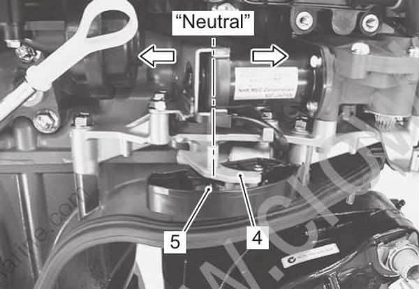
4. Clutch lever
5. Neutral switch
If out of specification:
- 1st; Check switch position adjustment, readjust if necessary.
- 2nd; Replace neutral switch.
After installing neutral switch, check for correct function by operating clutch lever.
