EVINRUDE ICON REMOTE CONTROL SYSTEM
Route all harnesses as shown and secure with tie straps.
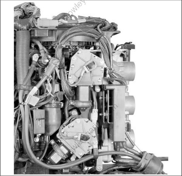
Install the flywheel cover and air silencer. Connect the battery cables at the battery.
IMPORTANT: Be sure to calibrate the throttle actuator stroke. Refer to Calibrate Actuator Stroke on p. 208.
ICON SYSTEM SETTINGS
Set Engine Identity (Instance)
In a multi-engine application, the transom position of the outboard must be identified on the network.
Engine identity is set by an Engine Identity Plug installed in the ESM. Outboards are identified as Instance 0 through 4, from port to starboard, up to five engines.
Each identity plug is stamped with its instance number.
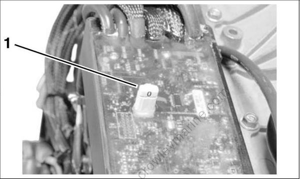
- Engine Identity plug
If the outboard is a single engine or the port engine in a multi-engine application, no changes are required.
For all other outboards, engine identity must be set by replacing the original plug (0) with the plug that corresponds to the outboard’s position on the transom.
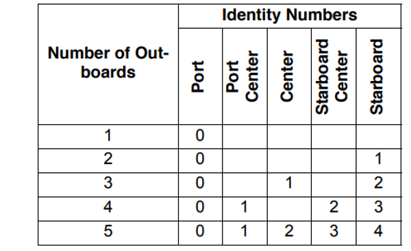
IMPORTANT: The Engine Identity Plug overrides any previous EMM instance setting.
Calibrate Actuator Stroke
After installation, dealer MUST use Evinrude Diagnostics software, version 5.1 or higher, to calibrate the actuators for correct throttle and shift stroke. Failure to calibrate shift stroke will lead to gearcase failure and possible loss of boat control not covered by warranty.
The Evinrude ICON actuators do not require periodic calibration. The shift and/or throttle actuator MUST be calibrated when the following services are performed on engines equipped with electronic shift and throttle:
Replacement of throttle or shift actuator
Replacement of Electro Servo Module (ESM)
Replacement of Throttle Position Sensor (TPS)
Throttle or shift linkage removal/installation
Powerhead removal/installation
Gearcase removal/installation
To calibrate the actuators, use the ICON tab of the Evinrude Diagnostics Settings screen.
In a multi-engine application, all outboards can be calibrated through one connection. Use the Engine Instance menu to select the engine instance on the screen.
IMPORTANT: If the ICON tab is not available, make sure the engine management software has been updated to the correct revision.
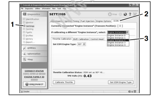
- Settings
- ICON tab
- Engine instance menu
Throttle Actuator Stroke
To set throttle stroke, click the Calibrate Throttle button. The actuator arm will move forward and back to find the mechanical limits of the throttle linkage. Evinrude Diagnostics reports when the process is complete.
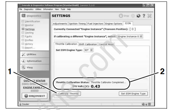
- Calibrate Throttle button
- Process complete message
Shift Actuator Stroke
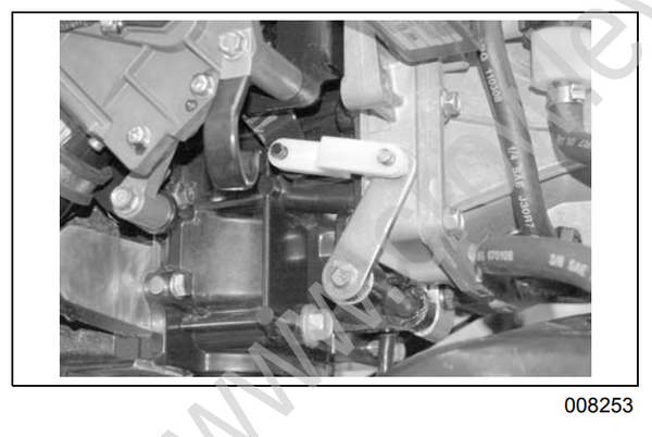
To set forward gear shift stroke:
- With the shift link disconnected, rotate the propeller and manually shift the outboard into forward gear with the shift lever.
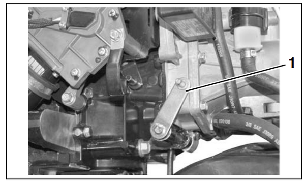
- Shift lever in forward
IMPORTANT: Make sure the gear is fully engaged and the lever is all the way forward.
Select FORWARD under Shift Position on the ICON screen. The actuator arm will move forward
Use the Nudge buttons to move the actuator arm forward or backward until the shift link aligns with the actuator arm and shift lever pins.
When the link and pins are exactly aligned, install the link and click the Save button. The actuator will move to the neutral position.
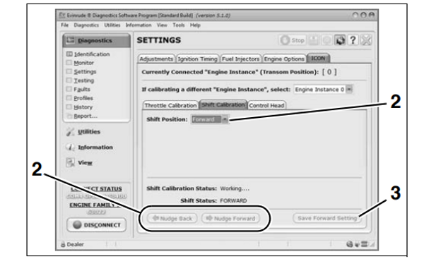
- Shift position
- Nudge buttons
- Save button
To set reverse gear shift stroke:
Remove shift link, but keep it installed on the actuator arm.
Rotate the propeller and manually shift the outboard into reverse gear with the shift lever.
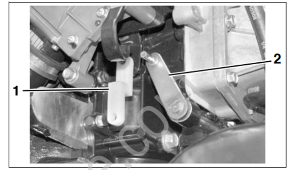
- Shift link installed on actuator
- Shift lever in reverse
IMPORTANT: Make sure the gear is fully engaged and the lever is all the way to the rear.
Select REVERSE button under Shift Position on the ICON screen. The actuator arm will move backward. Use the Nudge buttons to align the shift link.
When the link and pins are exactly aligned, install the link and click the Save button. The actuator will move to the neutral position.
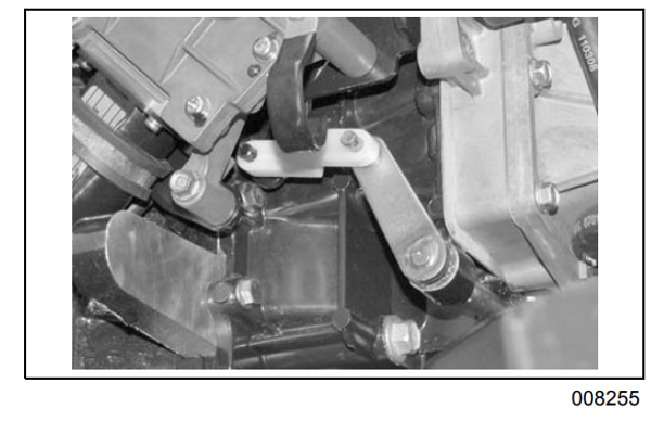
After forward and reverse strokes have been calibrated, the ESM calculates neutral position.
Install the shift link and secure with retainer clips and washers.
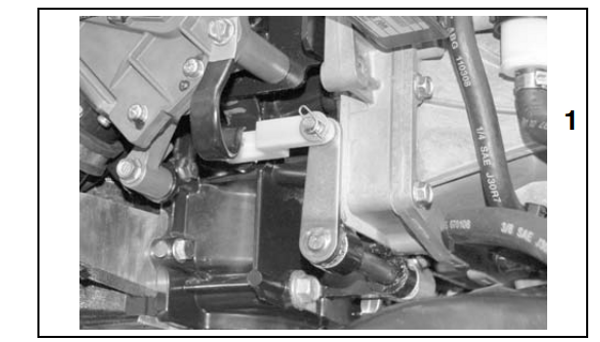
- Retainer clip and washer
Lock the retainers by moving the angled section behind the straight section.
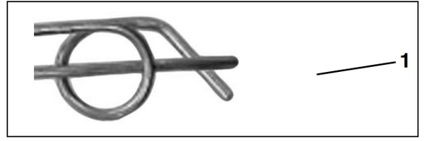
Locked Retainer Clip
- Angled section behind straight section
When installation is complete, shift the outboard with control (while rotating propeller). Rotate the propeller shaft back and forth to ensure the face of the clutch dog contacts the gear in both forward and reverse. With the outboard in neutral, make sure the propeller shaft turns freely with no contact between the clutch dog and gears.