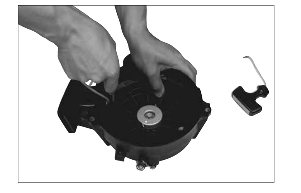
Step 1: Engine
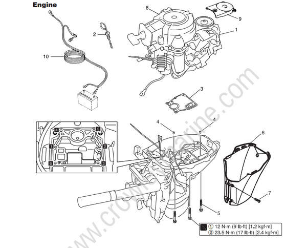
| Ref. No. |
Description | Q'ty | Remarks |
|---|---|---|---|
| 1 | Power Unit | 1 | |
| 2 | Oil Level Gauge | 1 | |
| 3 | Gasket | 1 | Do not reuse. |
| 4 | Dowel Pin | 2 | |
| 5 | Bolt | 6 | M8 L=35 mm |
| 6 | Drive Shaft Housing Cover | ||
| 7 | Screw | 2 | M5 L=30 mm |
| 8 | Recoil Starter | 1 | |
| 9 | Belt Cover | 1 | |
| 10 | Battery Cable | 1 |
Step 2: Magneto
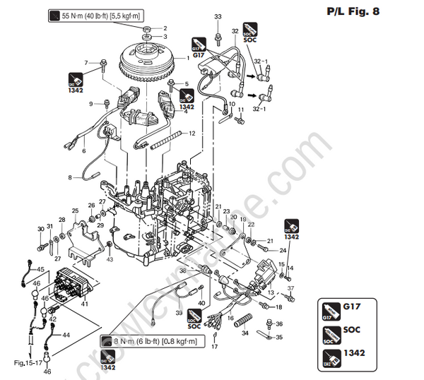
| Ref. No. |
Description | Q'ty | Remarks |
|---|---|---|---|
| 1 | Flywheel Cup (with Ring Gear) | 1 | |
| 2 | Nut, 12-P1.25 | 1 | M12 |
| 3 | Washer | 1 | |
| 4 | Exciter Coil | 1 | |
| 5 | Bolt | 2 | M6 L=30 mm |
| 6 | Alternator | 1 | for TE/TP & E/P |
| 7 | Bolt | 4 | for TE/TP & E/P |
| 8 | Pulser Coil | 1 | M6 L=30 mm |
| 9 | Screw | 2 | |
| 10 | Clamp, 6.5-47.5P | 1 | Alternator & Exciter Cable |
| 11 | Bolt | 1 | M6 L=16 mm |
| 12 | Spiral Tube Protector (ø10-100) | 1 | for TE/TP & E/P |
| 13 | C.D. Unit (CU7256) | 1 | |
| 14 | Bolt, 6-16 Pre-coated | 2 | M6 L=16 mm |
| 15 | Washer, 6-16-1.5 | 2 | |
| 16 | C.D. Unit Cord Ass’y | 1 | |
| 17 | Cable Terminal Plug | 2 | Light green & White Cable |
| 18 | Bolt | 1 | Ground Cable M6 L=12 mm |
| 19 | C.D. Unit Bracket | 1 | |
| 20 | Rubber Mount, 8.5-17 | 3 | |
| 21 | Washer, 6-16-1.5 | 6 | |
| 22 | Rubber Mount, 9-16-4.3 | 3 | |
| 23 | Collar, 6.2-9-7.4 | 3 | |
| 24 | Bolt | 3 | M6 L=25 mm |
| Ref. No. |
Description | Q'ty | Remarks |
|---|---|---|---|
| 25 | Electric Bracket | 1 | for TE/TP & E/P |
| 26 | Rubber Mount, 8.5-17 | 3 | for TE/TP & E/P |
| 27 | Washer, 6-16-1.5 | 6 | for TE/TP & E/P |
| 28 | Rubber Mount, 9-16-4.3 | 3 | for TE/TP & E/P |
| 29 | Collar, 6.2-9-7.4 | 3 | for TE/TP & E/P |
| 30 | Bolt | 3 | for TE/TP & E/P M6 L=20 mm |
| 31 | Clamp, 6.5-87P | 1 | for E/P |
| 32 | Ignition Coil | 1 | |
| 32-1 | Plug Cap (with Resistance) | 2 | |
| 33 | Bolt | 2 | M6 L=25 mm |
| 34 | Protector | 1 | ø34-70 for R |
| 35 | Clamp, 6.5-87P | 1 | for R |
| 36 | Bolt | 1 | for R M6 L=12 mm |
| 37 | Bolt | 1 | for R M6 L=12 mm |
| 38 | Oil Pressure Switch | 1 | |
| 39 | Separate Cord (Black) | 1 | |
| 40 | Cable Terminal Plug | 1 | |
| 41 | Power Tilt Solenoid Switch “A” | 1 | for TP/P |
| 42 | Bolt | 2 | for TP/P M6 L=20 mm |
| 43 | Nut | 2 | for TP/P M6 |
| 44 | Solenoid Switch Cord “A” | 1 | for TP/P |
| 45 | Solenoid Switch Cord “B” | 1 | for TP/P |
| 46 | Terminal Cap | 3 | for TP/P |
Step 3: Electric Parts
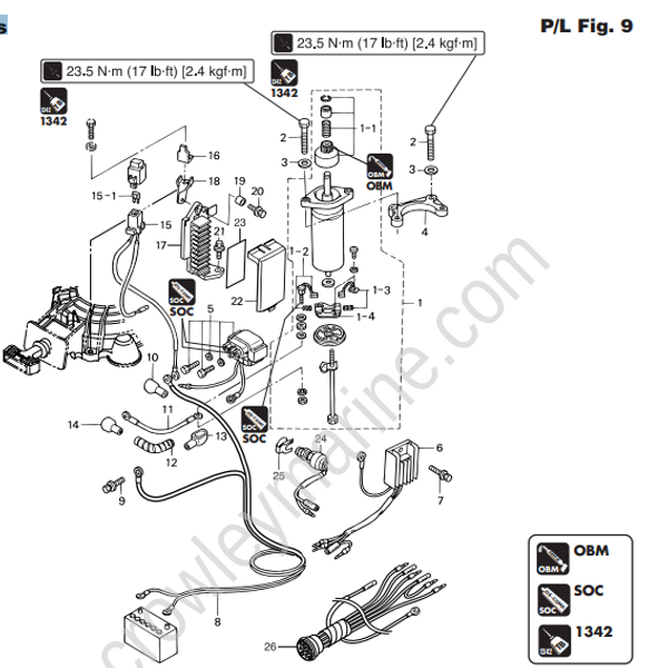
| Ref. No. |
Description | Q'ty | Remarks |
|---|---|---|---|
| 1 | Starter Motor (S106-12B) | 1 | for TE/TP & E/P |
| 1-1 | Pinion Ass’y | 1 | for TE/TP & E/P |
| 1-2 | Positive Brush (with Spring) | 1 | |
| 1-3 | Negative Brush (with Spring) | 1 | for TE/TP & E/P |
| 1-4 | Brush Holder | 1 | for TE/TP & E/P |
| 2 | Bolt | 4 | for TE/TP & E/P M8 L=30 mm |
| 3 | Washer | 4 | for TE/TP & E/P |
| 4 | Starter Motor Bracket | 1 | for TE/TP & E/P |
| 5 | Starter Solenoid | 1 | for TE/TP & E/P |
| 6 | Rectifier | 1 | for TE/TP & E/P |
| 7 | Bolt | 1 | for TE/TP & E/P M6 L=16 mm |
| 8 | Battery Cable (L=2500) | 1 | for TE/TP & E/P |
| 9 | Bolt | 1 | for TE/TP & E/P M6 L=10 mm |
| 10 | Terminal Cap | 1 | for TE/TP & E/P |
| 11 | Starter Cable | 1 | L=200 for TE/TP & E/P |
| 12 | Spiral Tube Protector | 1 | Starter Cable, ø10-100 for TE/TP & E/P |
| 13 | Terminal Cap | 1 | for TE/TP & E/P |
| 14 | Terminal Cap | 1 | for TE/TP & E/P |
| 15 | Fuse Cable | 1 | L=185 for TE/TP & E/P |
| 15-1 | Fuse (20A) | 2 | for TE/TP & E/P |
| 16 | Fuse Holder Stay | 1 | for TE/TP & E/P |
| 17 | Cable Terminal Holder | 1 | for TE/TP & E/P |
| 18 | Cable Terminal Holder Stay | 1 | for TE/TP & E/P |
| 19 | Collar, 6-8-6 | 1 | for TE/TP & E/P |
| Ref. No. |
Description | Q'ty | Remarks |
|---|---|---|---|
| 20 | Bolt | 1 | for TE/TP & E/P M6 L=12 mm |
| 21 | Bolt | 1 | for TE/TP & E/P M6 L=16 mm |
| 22 | Terminal Holder Cover | 1 | for TE/TP & E/P |
| 23 | Wiring Diagram Decal | 1 | for TE/TP |
| Wiring Diagram Decal | 1 | for E/P | |
| 24 | Neutral Switch | 1 | for TE/TP |
| 25 | Neutral Switch Actuator | 1 | for TE/TP |
| 26 | Cord Ass’y | 1 | for P |
Step 4: Intake Manifold & Fuel Pump
P/L Fig. 5
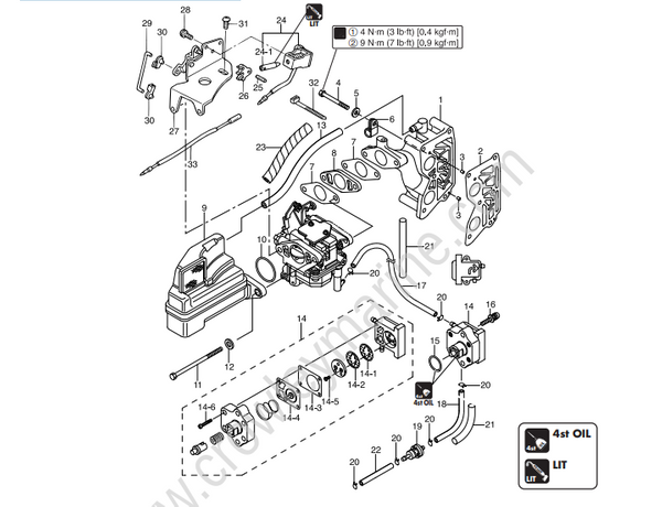
| Ref. No. |
Description | Q'ty | Remarks |
|---|---|---|---|
| 1 | Intake Manifold | 1 | |
| 2 | Intake Manifold Gasket | 1 | |
| 3 | Spring Pin, 3-10 | 2 | |
| 4 | Bolt | 6 | M6 L=53 mm |
| 5 | Washer | 6 | |
| 6 | Clamp, 6.14L | 1 | |
| 7 | Carburetor Gasket | 2 | |
| 8 | Insulator | 1 | |
| 9 | Intake Silencer | 1 | |
| 10 | O-Ring, 2-35 | 1 | |
| 11 | Bolt | 2 | Carburetor M6 L=95 mm |
| 12 | Washer | 2 | |
| 13 | Rubber Hose | 1 | |
| 14 | Fuel Pump | 1 | Mark “D” |
| 14-1 | Check Valve (R) | 1 | Black |
| 14-2 | Check Valve (P) | 1 | White |
| 14-3 | Pump Body Gasket | 1 | |
| 14-4 | Pump Diaphragm | 1 | |
| 14-5 | Screw | 2 | M3 L=8 mm |
| 14-6 | Screw | 4 | M4 L=18 mm |
| Ref. No. |
Description | Q'ty | Remarks |
|---|---|---|---|
| 15 | O-Ring, 2.62-18.72 | 1 | Do not reuse. |
| 16 | Screw | 2 | M6 L=25 mm |
| 17 | Rubber Hose | 1 | |
| 18 | Rubber Hose | 1 | |
| 19 | Fuel Filter | 1 | |
| 20 | Clip ø10 | 6 | |
| 21 | Protector | 2 | ø12-120 |
| 22 | Rubber Hose | 1 | |
| 23 | Spiral Tube Protector | 1 | ø10-100 for E/P |
| 24 | Choke Solenoid | 1 | for E/P |
| 24-1 | Plunger | 1 | for E/P |
| 25 | Spring Pin, 3-12 | 1 | for E/P |
| 26 | Choke Solenoid Hook | 1 | for E/P |
| 27 | Choke Solenoid Bracket Ass’y | 1 | for E/P |
| 28 | Screw | 3 | for E/P M4 L=8 mm |
| 29 | Link Rod | 1 | for E/P |
| 30 | Rod Snap, 1.2 | 2 | for E/P |
| 31 | Screw | 1 | for E/P M5 L=10 mm |
| 32 | Band | 1 | for E/P |
| 33 | Assist Cord 1 (Blue) | for E |
Step 5: Pulley & Timing Belt
P/L Fig. 4
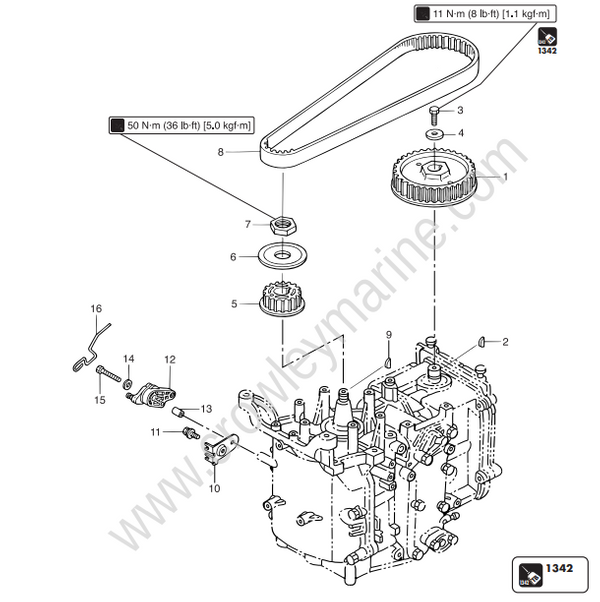
| Ref. No. |
Description | Q'ty | Remarks |
|---|---|---|---|
| 1 | Driven Pulley | 1 | (Black) Camshaft Pulley |
| 2 | Key | 1 | |
| 3 | Bolt, 6-20 Pre-coated | 1 | M6 L=20 mm |
| 4 | Washer, 6.5-19-3.2 | 1 | |
| 5 | Drive Pulley | 1 | Timing Pulley |
| 6 | Belt Guide | 1 | |
| 7 | Nut | 1 | |
| 8 | Timing Belt | 1 | |
| 9 | Key | 1 | |
| 10 | Throttle Cable Bracket | 1 |
| Ref. No. |
Description | Q'ty | Remarks |
|---|---|---|---|
| 11 | Bolt | 1 | M6 L=12 mm |
| 12 | Throttle Dram | 1 | |
| 13 | Spacer, 6.2-9-15.7 | 1 | |
| 14 | Washer, 6.5-16-1.5 | 1 | |
| 15 | Bolt | 1 | M6 L=30 mm |
| 16 | Throttle Rod | 1 |
Step 6: Cylinder Head & Oil Pump
P/L Fig. 3
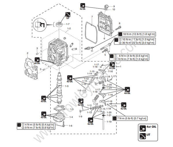
| Ref. No. |
Description | Q'ty | Remarks |
|---|---|---|---|
| 1 | Cylinder Head Complete | 1 | Camshaft & Oil Pump & Valve |
| 1-2 | Cylinder Head | 1 | |
| 1-3 | Camshaft | 1 | |
| 1-4 | Oil Pump | 1 | |
| 1-5 | Oil Pump Gasket | 1 | Do not reuse. |
| 1-6 | Bolt | 3 | M6 L=35 mm |
| 1-7 | Oil Seal, 18-35-8 | 1 | Do not reuse. |
| 1-8 | Intake Valve | 2 | |
| 1-9 | Exhaust Valve | 2 | |
| 1-10 | Intake Valve Stem Seal | 2 | Black Do not reuse. |
| Ref. No. |
Description | Q'ty | Remarks |
|---|---|---|---|
| 1-11 | Exhaust Valve Stem Seal | 2 | Green Do not reuse. |
| 1-12 | Valve Spring | 4 | L=38.3 |
| 1-13 | Valve Spring Seat | 4 | |
| 1-14 | Retainer | 4 | |
| 1-15 | Cotter | 8 | |
| 1-16 | Rocker Arm | 4 | |
| 1-17 | Adjusting Screw | 4 | |
| 1-18 | Adjusting Nut | 4 | |
| 1-19 | Rocker Arm Shaft | 1 | |
| 1-20 | Rocker Shaft Spring | 2 | L=25 mm |
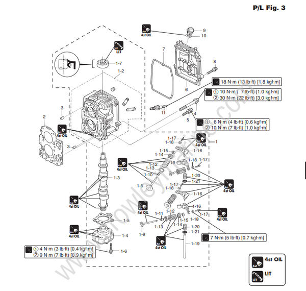
| Ref. No. |
Description | Q'ty | Remarks |
|---|---|---|---|
| 1-21 | Washer, 13.2-21.7-2 | 2 | |
| 2 | Cylinder Head Gasket | 1 | Do not reuse. |
| 3 | Dowel Pin, 6-12 | 2 | |
| 4 | Cylinder Head Bolt 8-50 | 6 | M8 L=50 mm |
| 5 | Bolt | 3 | M6 L=25 mm |
| 6 | Cylinder Head Cover | 1 | |
| 7 | Cylinder Head Cover Gasket | 1 | Do not reuse. |
| 8 | Bolt | 4 | M6 L=25 mm |
| 9 | Engine Oil Filler Cap | 1 | |
| 10 | O-Ring, 3.1-24.4 | 1 | Do not reuse. |
| 11 | Spark Plug | 2 | NGK : DCPR6E |
Step 7: Cylinder & Crank Case
P/L Fig. 1
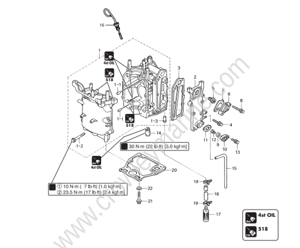
| Ref. No. |
Description | Q'ty | Remarks |
|---|---|---|---|
| 1 | Cylinder-Crank Case | 1 | |
| 1-1 | Dowel Pin, 6-12 | 2 | |
| 1-2 | Bolt, 8-50 | 8 | M8 L=50 mm |
| 1-3 | Nipple, 10-32 | 1 | |
| 2 | Exhaust Cover | 1 | |
| 3 | Exhaust Cover Gasket | 1 | |
| 4 | Bolt | 5 | M6 L=25 mm |
| 5 | Thermostat | 1 | Mark “60” |
| Thermostat | 1 | Mark “70” Option | |
| 6 | Thermostat Cap | 1 | |
| 7 | Thermostat Cap Gasket | 1 | |
| 8 | Bolt | 2 | M6 L=20 mm |
| 9 | Anode | 1 |
| Ref. No. |
Description | Q'ty | Remarks |
|---|---|---|---|
| 10 | Anode Cap | 1 | |
| 11 | Anode Cap Gasket | 1 | |
| 12 | Bolt | 1 | M6 L=16 mm |
| 13 | Bolt | 2 | M6 L=20 mm |
| 14 | Plunger | 1 | |
| 15 | Rubber Hose | 1 | for Water Nipple |
| 16 | Oil Level Gauge | 1 | |
| 17 | Oil Strainer | 1 | |
| 18 | Rubber Hose | 1 | |
| 19 | Lead Wire Band, 158 | 2 | |
| 20 | Engine Basement Gasket | 1 | |
| 21 | Bolt (8-35) | 6 | M8 L=35 mm |
| 22 | Washer | 6 |
Step 8: Piston & Crankshaft
P/L Fig. 2
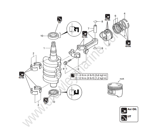
| Ref. No. |
Description | Q'ty | Remarks |
|---|---|---|---|
| 1 | Crankshaft | 1 | |
| 2 | Bearing (Black) | 4 | t=1.5 0-0.006 |
| Bearing (Brown) | 4 | t=1.5 -0.006 -0.012 | |
| 3 | Piston | 2 | |
| Piston (0.5 mm O/S) | 2 | Option | |
| 4 | Piston Ring Top | 2 | |
| Piston Ring Top (0.5 mm O/S) | 2 | Option | |
| 5 | Piston Ring 2nd | 2 | |
| Piston Ring 2nd (0.5 mm O/S) | 2 | Option | |
| 6 | Piston Ring Oil | 2 |
| Ref. No. |
Description | Q'ty | Remarks |
|---|---|---|---|
| Piston Ring Oil (0.5 mm O/S) | 2 | Option | |
| 7 | Piton Pin | 2 | |
| 8 | Piton Pin Clip | 4 | Do not reuse. |
| 9 | Connecting Rod | 2 | |
| 9-1 | Connecting Rod Bolt | 4 | |
| 10 | Oil Seal, 30-45-8 | 2 | Do not reuse. |
Step 9: Recoil Starter
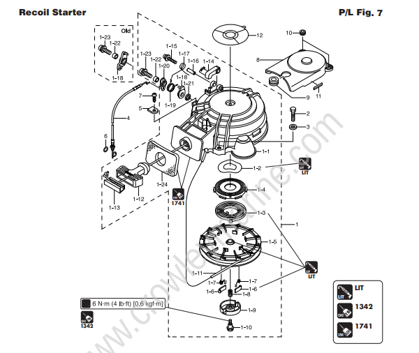
| Ref. No. |
Description | Q'ty | Remarks |
|---|---|---|---|
| 1 | Recoil Starter | 1 | |
| 1-1 | Starter Case | 1 | |
| 1-2 | Wave Washer | 1 | |
| 1-3 | Starter Spring | 1 | t=0.67 |
| 1-4 | Starter Spring Case | 1 | |
| 1-5 | Reel | 1 | |
| 1-6 | Ratchet | 2 | |
| 1-7 | Return Spring | 2 | |
| 1-8 | Friction Spring | 1 | |
| 1-9 | Friction Plate | 1 | |
| 1-10 | Starter Shaft Bolt | 1 | |
| 1-11 | Starter Rope | 1 | ø4.5-1620 |
| 1-12 | Starter Handle | 1 | |
| 1-13 | Rope Anchor | 1 | |
| 1-14 | Starter Lock (Black) | 1 | |
| 1-15 | Screw | 1 | M4 L=30 mm |
| 1-16 | Collar, 4-6-21 | 1 | |
| 1-17 | Starter Lock Spring | 1 | |
| 1-18 | Starter Lock Cam | 1 |
| Ref. No. |
Description | Q'ty | Remarks |
|---|---|---|---|
| 1-19 | Starter Lock Cam Spring | 1 | |
| 1-20 | Starter Lock Lever | 1 | |
| 1-21 | Washer | 1 | |
| 1-22 | Collar, 6.2-9-12.3 | 1 | |
| 1-23 | Screw | 1 | M6 L=25 mm |
| 1-24 | Starter seal rubber | 1 | |
| 2 | Bolt | 3 | M6 L=25 mm |
| 3 | Washer, 6.5-16-1.5 | 3 | for R |
| Washer, 6.5-16-1.5 | 2 | for TE/TP & E/P | |
| 4 | Starter Lock Cable | 1 | |
| 5 | Stopper | 1 | |
| 6 | O-Ring, 1.5-2.5 | 1 | Do not reuse. |
| 7 | Tapping Screw, 5-12 | 1 | M5 L=12 mm |
| 8 | Belt Cover | 1 | |
| 9 | Rubber Mount, 2.5-20 | 1 | |
| 10 | Grommet, 13-2 | 2 | |
| 11 | Resistance Spark Plug Decal | 1 | |
| 12 | Caution Decal “B” | 1 |
Step 10: Top Cowl
P/L Fig.20
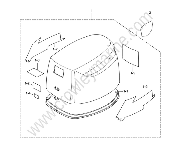
| Ref. No. |
Description | Q'ty | Remarks |
|---|---|---|---|
| 1 | Top Cowl | 1 | UNIQUE |
| 1-1 | Top Cowl Seal | 1 | L=1295 mm |
| 1-2 | Decal Set | 1 | UNIQUE |
| Decal Set | 1 | UNIQUE | |
| 1-3 | Caution Decal “A” | 1 |
| Ref. No. |
Description | Q'ty | Remarks |
|---|---|---|---|
| 1-4 | Oil Pressure Decal | 1 | |
| 2 | PT Decal | 2 | for TP/P |
Step 11: 3. Inspection Items
1) Inspection of Compression Pressure
Run engine 5 minutes to warm up, and then stop.
Shift gear into neutral (N).
Remove lock plate (of stop switch lanyard) from stop switch.
Remove lock plate (of stop switch lanyard) from stop switch before measuring compression pressure. This will prevent
engine from accidental starting.
- Remove all plug caps and then all spark plugs
Clean areas around spark plugs on the cylinder before removing spark plugs to prevent dirt from entering cylinder.
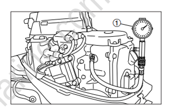
- Install compression gauge to plug hole
Compression gauge 1 :
Use commercially available item.
- Fully open throttle, crank engine until compression gauge indication stabilizes, and then measure compression pressure.
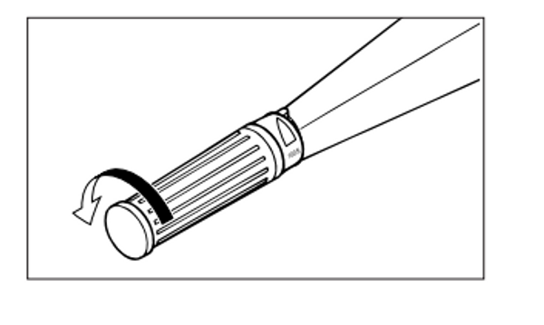
Compression Pressure (Reference) :500 r/min
: 0.88 MPa (128 psi) [9.0 kgf/cm2]
Compression pressure varies depending on the cranking speed, and normally changes at least as much as approximately 10%.
- If compression pressure is below specified value or varies among cylinders, put small amount of engine oil into cylinders, and perform the test again.
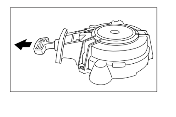
If compression pressure of a cylinder increases after the above measure, check pistons and piston rings of the cylinder for wear. Replace if necessary.
If compression pressure does not increase after the above measure, check valve clearances, valves, valve seats, cylinder sleeves, cylinder head gaskets and cylinder head. Adjust or replace if necessary.
Step 12: 2) Inspection of Oil Pressure
Spread rag below oil pressure switch.
Remove oil pressure switch and connect oil pressure gauge (1) to switch hole.
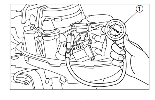
Do not overtighten, or Block damage can occur.
Use commercially available oil pressure gauge
(1/8" npt test port).
Use the instrument applicable to 1 MPa (142
psi) [10 kgf/cm2].
Start engine and run 5 minutes to warm up at idling revolution speed.
Measure oil pressure. If the pressure is below specified value, check oil pump for oil leak, and oil strainer and plunger.
Hydraulic Pressure (Reference)
:Oil Temperature 70°C (167°F)
0.10MPa (14 psi) [1.0 kgf/cm2] or higher at 950 r/min
0.33 MPa (47 psi) [3.3 kgf/cm2] or higher at 5,000 r/min
Step 13: Inspection of Valve Clearance
Perform adjustment of valve clearances when engine is cold.
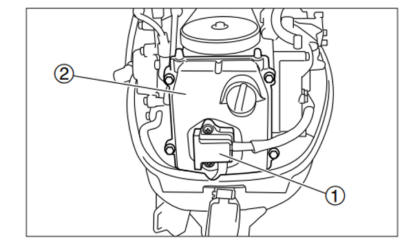
Remove starter lock cable (Upper), and then recoil starter and belt cover.
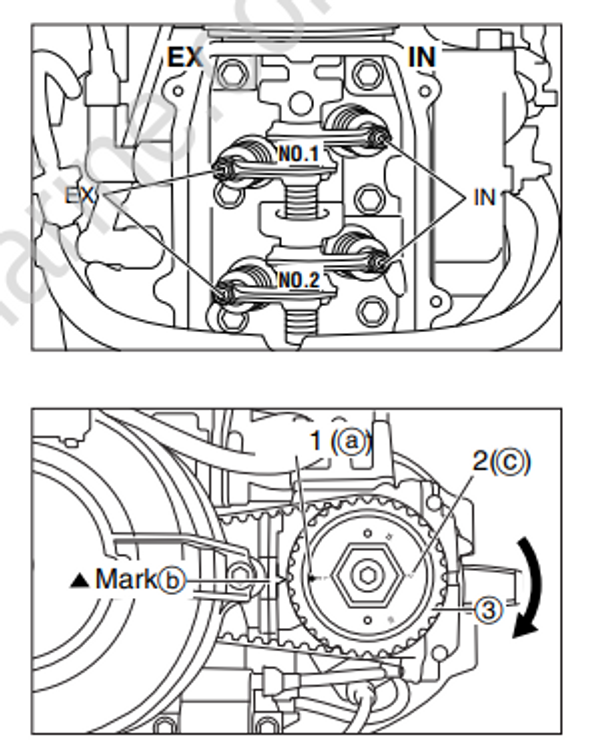
Remove fuel pump 1.
Disconnect plug cap connection, and then, remove spark plug and cylinder head cover 2.
When removing or installing cylinder head cover, use 10mm ring wrench with large offset angle.
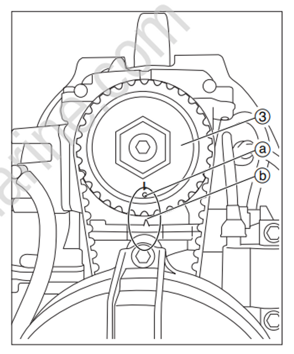
- Operate recoil starter slowly to bring "●1" mark (a) of cam shaft pulley 3 to "▲" mark (b) of cylinder head.
No.1 piston is to be at top dead center of compression stroke.
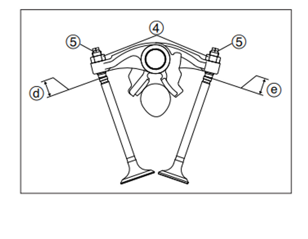
- Check and adjust No. 1 cylinder's intake and exhaust valve clearances. Adjust gap if it is out of specified range.
Valve Clearance (when engine is cold):
(IN) Intake valve a : 0.13 - 0.17 mm (0.0051 - 0.0067 in)
(EX) Exhaust valve b : 0.18 - 0.22 mm (0.0071 - 0.0087 in)
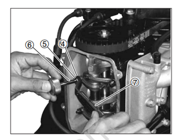
- Loosen rocker arm lock nut (4), and turn adjusting screw (5) so that valve clearances are within the specified range.
Turning adjust screw (5) clockwise makes valve clearance smaller.
Turning adjust screw (5) counterclockwise makes valve clearance larger.
Valve clearance driver 6 :
P/N. 341444
Torque wrench 7
Thickness gauge :
Use commercially available item.
- Tighten rocker arm lock nut (4) to specified torque, and check valve clearance again. Readjust if necessary.
Rocker arm lock nut 4 :
7 N · m (5 lb · ft) [0.7 kgf · m]
Valve Clearance (when engine is cold):
(IN) Intake valve a : 0.13 - 0.17 mm (0.0051 - 0.0067 in)
(EX) Exhaust valve b : 0.18 - 0.22 mm (0.0071 - 0.0087 in)
Rotate flywheel clockwise to bring "2" mark c of cam shaft pulley (3) to "▲" mark b of cylinder head.
Check and adjust No. 2 cylinder's intake and exhaust valve clearances. Adjust gap if it is out of specified range.
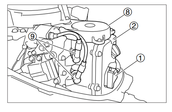
Attach new O ring, cylinder head cover (2), fuel pump (1), all spark plugs, recoil starter, and belt cover (8).
Reconnect starter lock cable (Upper).
Reconnect plug cap (9).
Step 14: Removing Power Unit
Disconnect starter lock cable (upper).
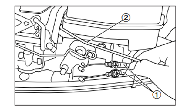
Disconnect throttle wire (1) and choke link rod (2). (Tiller handle model)
Remove throttle cable and shift cable. (Remote Control Model)
- Disconnect remote controller harness coupler, and then, remove remote controller harness. (Remote Control Model)
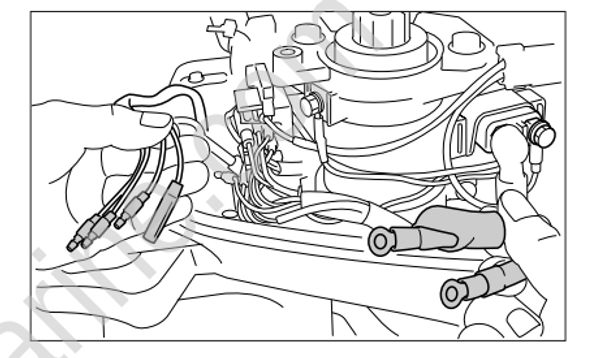
- Disconnect battery cords (3) and (4) (Electric starter model) (3) Disconnect ground wire of PT solenoid (4). (PT Model)
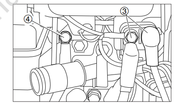
- Disconnect PT solenoid coupler (5) and PT leads (6). (PT Model)
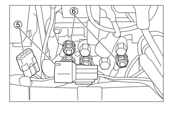
- Disconnect all electrical leads. Remove cord holder bolts (2) (7), and then, remove all leads from cord holder (8). (PT Model)
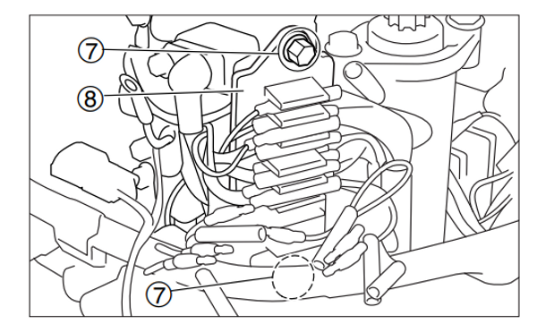
Remove oil level gauge.
Disconnect cooling water (pilot water) hose (9) and fuel hose (10).
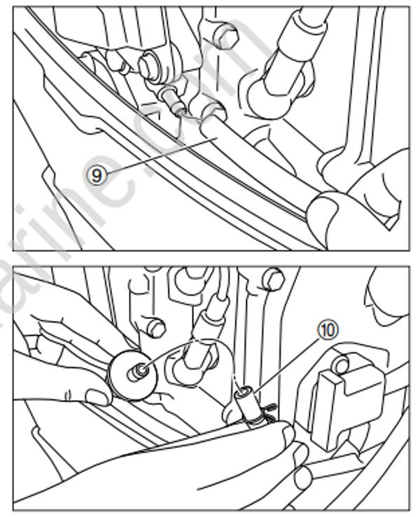
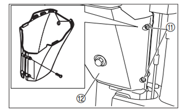
- Remove screw (11) (2), and then, remove drive shaft housing cover (12).
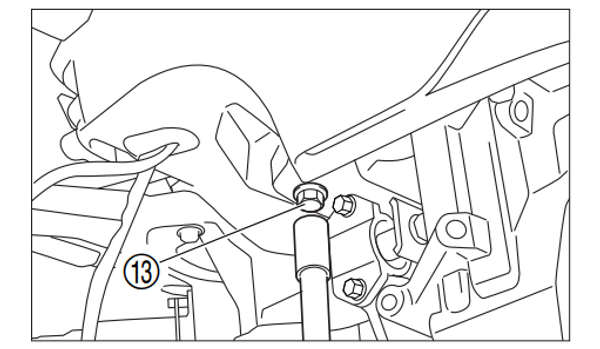
- Remove power unit by removing bolts (13) (6) and then hoisting it.
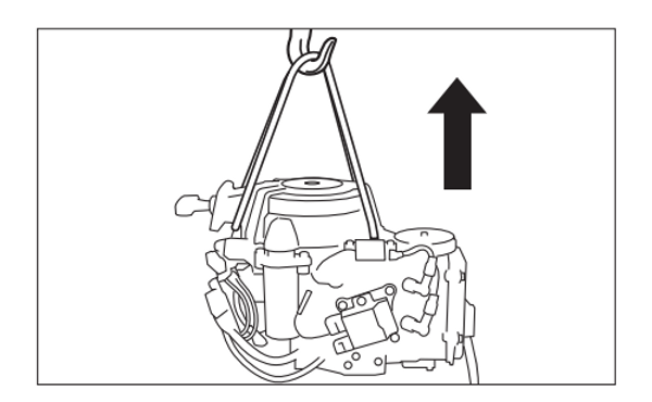
When hoisting power unit, perform the work carefully while checking if wires and hoses are caught by other parts.
Before removing power head ass'y, note arrangement of oil strainer hose.
Loosen power unit mounting bolts in the order reverse of tightening.
- Remove gasket and dowel pins (2).
Step 15: Removing Plunger and Oil Strainer
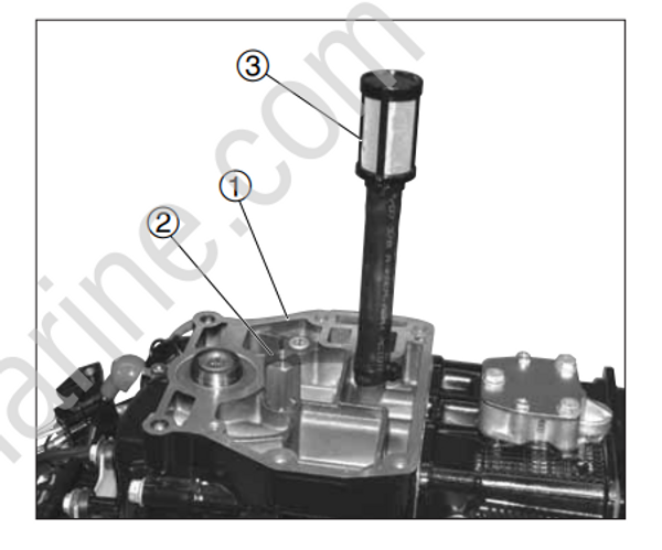
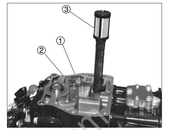
Put removed power head ass’y (1) upside down on the work bench.
Remove plunger 2 from power head ass'y (1).
Remove oil strainer 3 from power head ass'y (1).
Step 16: Inspection of Plunger and Oil Strainer
Check plunger for clogging and deposition. Use small bladed screw driver to check operation of plunger valve by pushing it down. Clean, or replace if necessary.
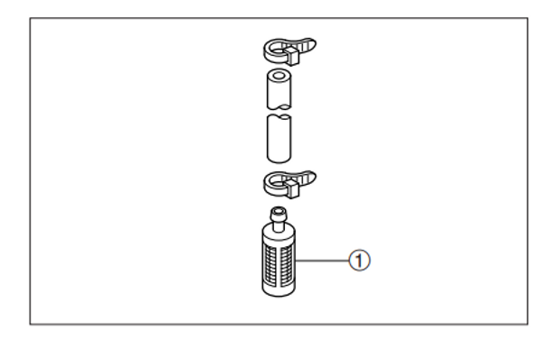
Check oil strainer (1) for dirt and deposition. Clean, or replace if necessary.
Step 17: Flywheel and electrical components
- Remove recoil starter and belt cover.
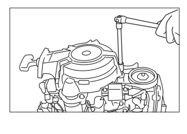
- Loosen flywheel nut
Flywheel puller kit :
P/N. 5041743
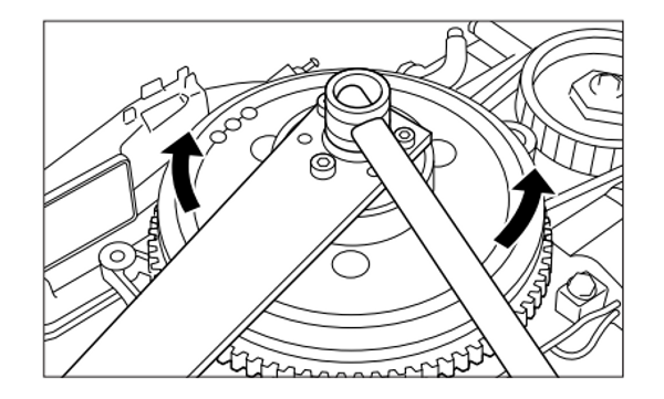
- Remove flywheel and key
Flywheel puller kit :
P/N. 5041743
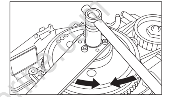
Screw puller onto crankshaft end until flywheel is disengaged from tapered section of crankshaft.
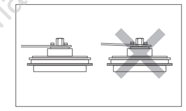
To prevent damages to engine and special tools, tighten flywheel puller set bolts evenly and keep flywheel puller parallel to flywheel while working.
Disconnect alternator, exciter coil and pulsar coil lead wires.
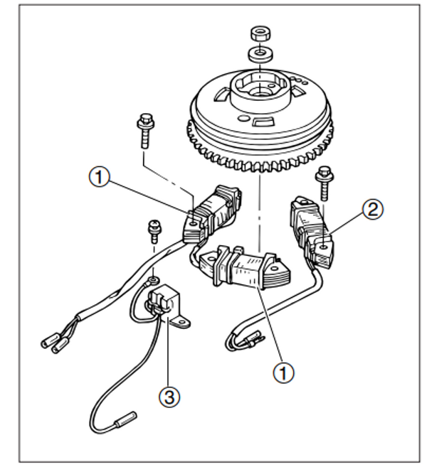
Remove bolts of alternator 1 and exciter coil 2 (2 each), and then, alternator and exciter coil.
Remove screws (2) of pulser coil 3, and then, pulser coil.
Step 18: Removing Timing Belt and Pulley
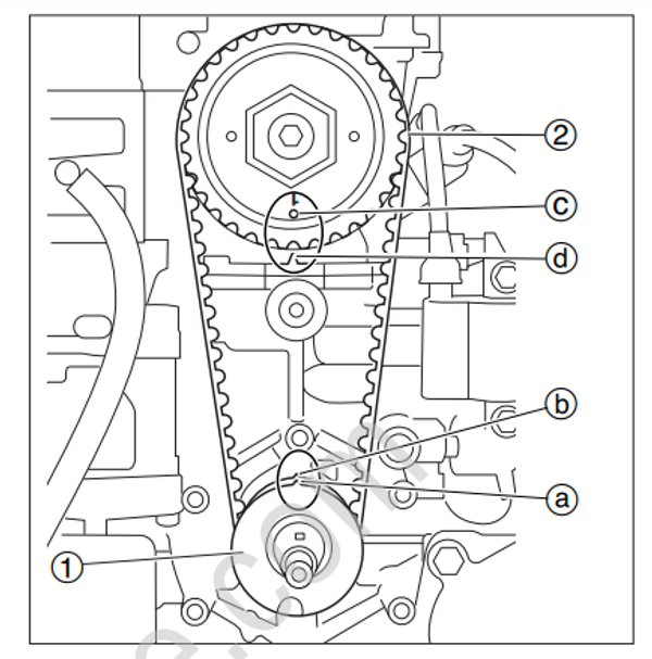
- Turn timing pulley (1) clockwise to bring "▲" mark (a) of belt guide to "▲" mark (b) of cylinder block, and check that "●1" mark (c) of cam shaft pulley (2) and "▲" mark (d) of cylinder head are aligned with each other.
No.1 piston is to be at top dead center of compression stroke.
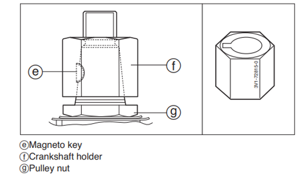
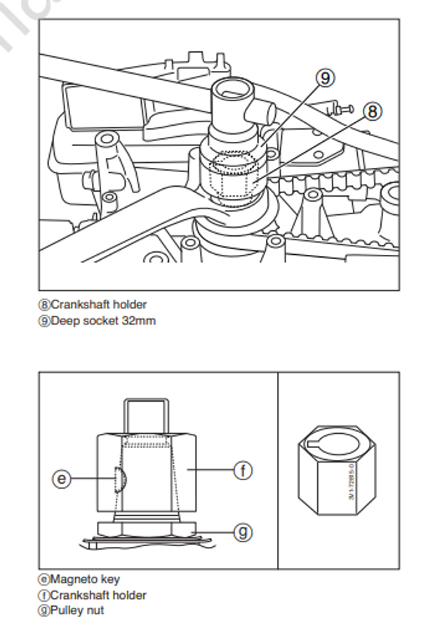
- Attach crankshaft holder (5) to crankshaft and secure it.
- Loosen timing pulley nut (3).
Remove belt guide (4).
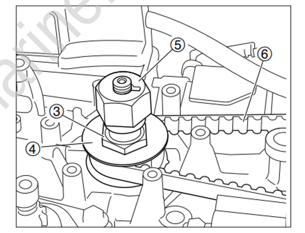
Use 32mm socket wrench and 30mm ring wrench for this step.
When loosening nut (3) of timing pulley (1), hold cam shaft pulley (2) to prevent it from being turned.
Keep timing belt (6) engaged as a means of precaution.
Crank Shaft Holder (5) : P/N. 5041745
- Remove bolt (7) of cam shaft pulley (2), and then cam shaft pulley.
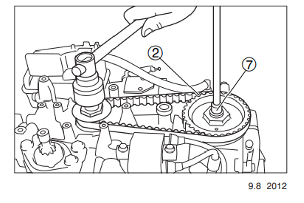
When loosening cam shaft pulley bolt, use crank shaft holder to prevent cam shaft pulley from turning.
- Remove timing belt 6 from cam shaft pulley 2 side, and then, from timing pulley side.
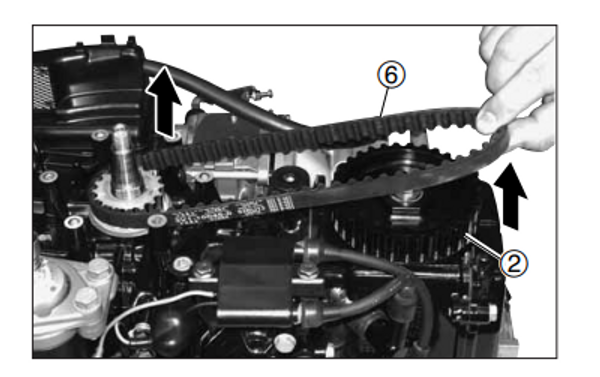
• Do not turn timing pulley (crank shaft) or cam shaft pulley with timing belt removed. Doing so can make pistons and valves interfere with each other, possibly resulting in damages to these parts.
• If Re-using, pay attention to install belt in the same direction of rotation when removed numbers up or numbers down.
- Remove timing pulley (8) and then key (9).
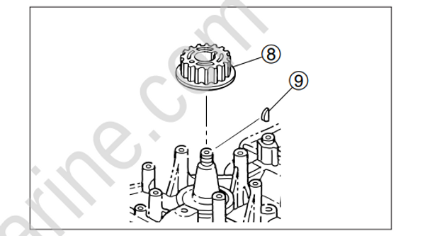
Remove timing pulley and cam shaft pulley while lifting them up horizontally.
Step 19: Inspection of Timing Belt
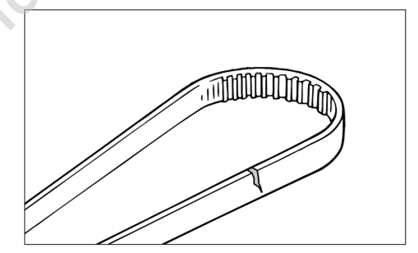
- Check timing belt for crack, damage and wear on both faces. Replace if necessary.
Step 20: Installation of Pulley and Timing Belt
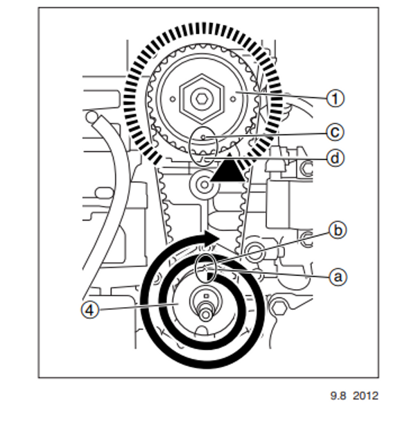
- Install cam shaft pulley, bring "●1" mark (a) of cam shaft pulley 1 to "▲" mark (b) of cylinder head, and then, temporally tighten bolt (2).
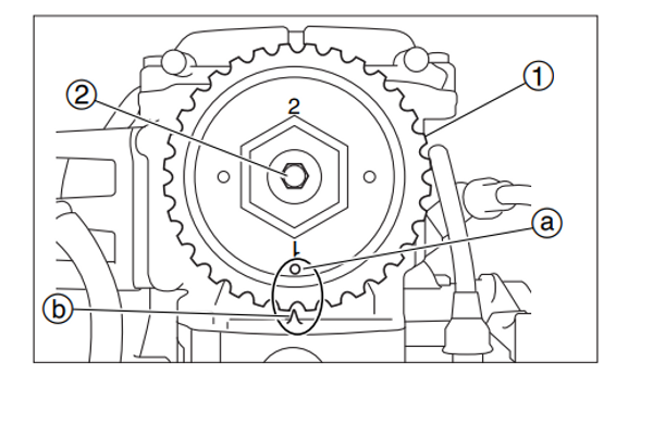
No.1 piston is to be at top dead center of compression stroke.
When reusing cam shaft pulley bolt, apply ThreeBond 1342 to thread.
Do not turn timing pulley or cam shaft pulley with timing belt removed. Doing so can make pistons and valves interfere with each other, possibly resulting in damages to these parts.
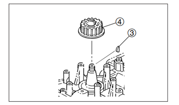
- Attach key (3) and then timing pulley (4)
- Check that “▲” mark (c) of timing pulley (4) is aligned with “▲” mark (d) of cylinder block.
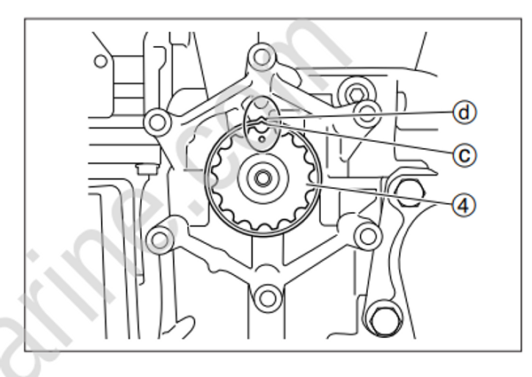
No.1 piston is to be at top dead center of compression stroke.
- Attach timing belt (5) to timing pulley with its part number side facing upward, and then to cam shaft pulley.
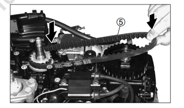
* Be careful not give damage to timing belt when installing.
* Do not twist timing belt, bring inside out, or bend sharp, or it may be damaged.
* Be careful not to allow oil or grease to adhere to timing belt.
- Turn timing pulley (4) clockwise twice, and check that locating marks (a) (b) and (c) (d) of pulleys (1) and (4) are aligned with each other respectively.
- Tighten cam shaft pulley (1) to specified torque.
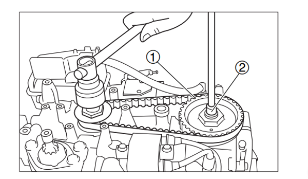
Tighten bolt while holding crank shaft with crank shaft holder to fix timing belt.
Cam Shaft Pulley Bolt (2): 11 N · m (8 lb · ft) [1.1 kgf · m]
- Put belt guide (6), and secure it with nut (7) by tightening the nut temporarily.
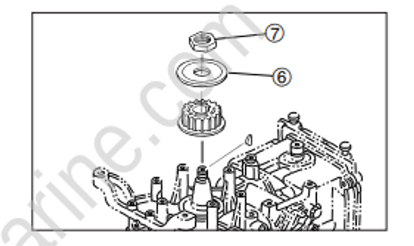
- Tighten timing pulley nut to specified torque.
- Put pulley nut with chamfered face down.
- Use 32mm socket wrench (9) and 30mm spanner wrench for this step.
Crankshaft holder (8) : P/N. 5041745
Timing Pulley Nut : 50 N · m (36 lb · ft) [5.0 kgf · m]
Step 21: Removing Cylinder Head
No.1 piston is to be at top dead center of compression stroke.
Removal or installation of parts can be made easier when some of them are assembled together.
Remove power unit. (Refer to the section for removing power unit.)
Remove magneto related parts from power unit.
Remove intake manifold, carburetor and fuel pump.
Remove electrical system parts from power unit.
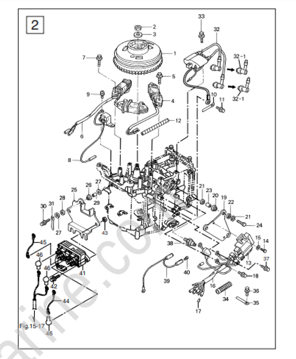
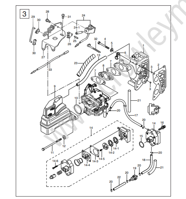

- Remove cam pulley and cylinder head cover. Remove hose.
For the procedure, refer to "Removing Timing Belt and Pulley" in Chapter 5.
- Remove cylinder head bolts in the reverse sequence of order shown, and remove cylinder head.
Do not scratch or give damage to mating surfaces of cylinder head and cylinder block.
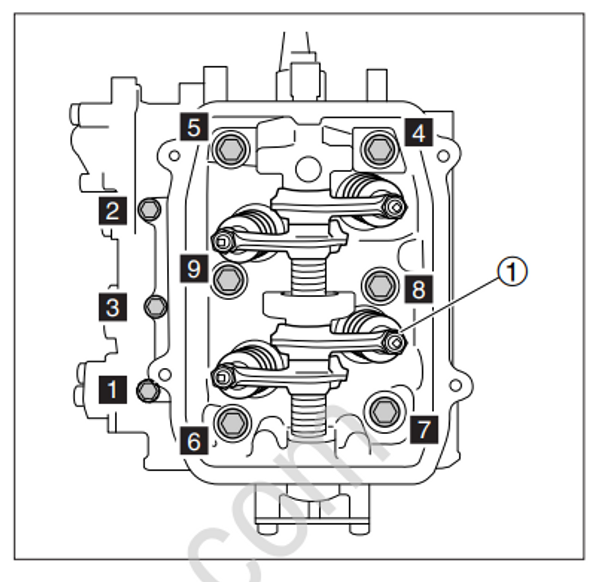
Loosen rocker arm lock nut (1), and loosen adjusting screw as much as possible.
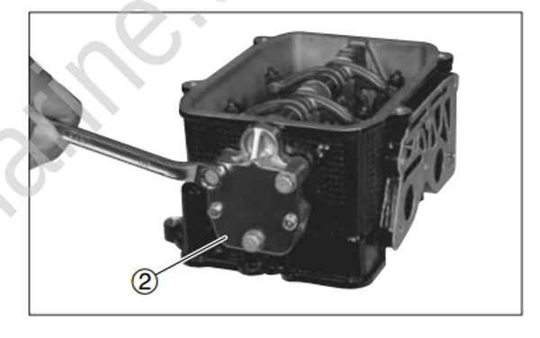
Remove oil pump ass'y (2).
- Remove rocker arm (3), spring (4), washer 5 and rocker arm shaft (6).
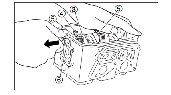
Push in flat head driver with rag and pull the part out downward slowly.
Pull the shaft while holding other parts with a hand.
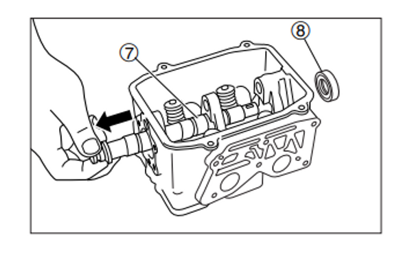
- Remove cam shaft (7)
Remove cam shaft slowly taking care not to touch journal.
- Remove oil seal (8).
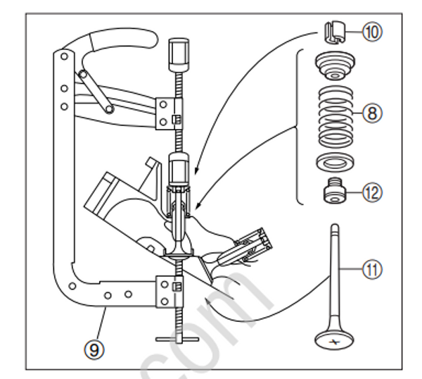
- Compress valve spring (8) using a commercially available valve spring compressor (9), remove cotters (10), and then, remove spring (8) and valve (11).
Valves, springs and other related parts should be arranged in the order they are removed.
Use attachment with inner diameter of 23.5mm.
If valve spring compressor is not used, put cylinder head on the folded rag to prevent valves from being damaged.
- Remove stem seal (12).
Step 22: Inspection of Valve Spring
- Measure valve spring free length (a). Replace if the length is less than specified value.
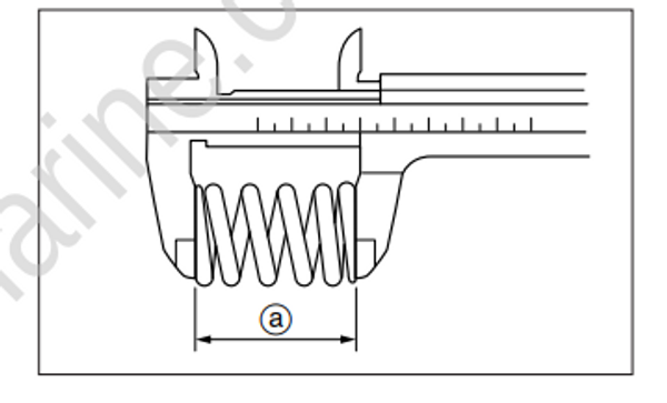
Valve Spring Free Length a : Standard Value
38.3 mm (1.51 in)
Functional Limit :
38.6 mm (1.45 in)
Step 23: Inspection of Valve
- Check valve for dent and wear on the face. Replace if necessary.
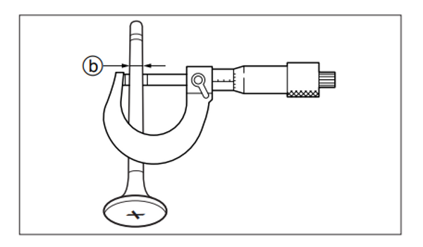
- Measure valve stem outer diameter b. Replace if it is less than specified value.
Valve Stem Outer Diameter b : Standard Value
Intake Side : 5.48 mm (0.2157 in)
Exhaust Side : 5.46 mm (0.2150 in)
Functional Limit :
Intake Side : 5.46 mm (0.2150 in)
Exhaust Side : 5.44 mm (0.2142 in)
Step 24: Inspection of Valve Guide
Before inspecting valve guide, check that valve stem outer diameter is within specified limit.
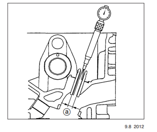
- Measure valve guide inner diameter a. Replace cylinder head if the inner diameter is over specified value.
Valve Guide Inner Diameter a : Standard Value
Intake/Exhaust Side : 5.51 mm (0.2169 in)
Functional Limit :
Intake Side : 5.55 mm (0.2185 in)
Exhaust Side : 5.57 mm (0.2193 in)
- Obtain clearance between valve guide and valve stem by calculating as described below. Replace cylinder head and/or valve if the clearance is over specified value.
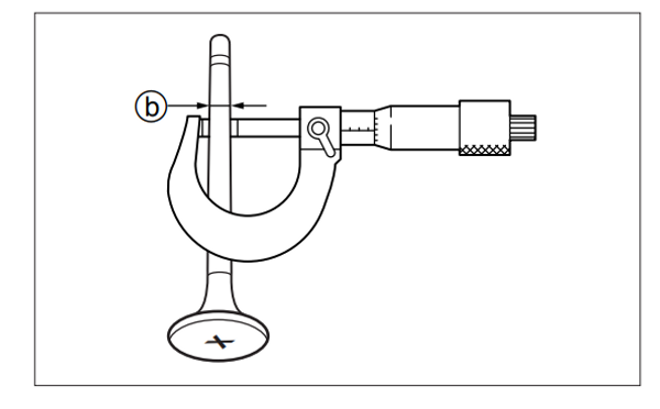
Clearance between valve guide and valve stem =
Valve Guide Inner Diameter a - Valve Stem
Outer Diameter b :
Intake Side : 0.008-0.040 mm (0.00031-0.00157 in)
Exhaust Side : 0.025-0.057 mm (0.00098-0.00224 in)
Functional Limit :
Intake Side : 0.070mm (0.00276 in)
Exhaust Side : 0.100 mm (0.00394 in)
Step 25: Inspection of Valve Seat
Remove carbon built up on the valve.
Apply a thin, even layer of Mechanic's blueing dye (Dykem) onto the valve seat.
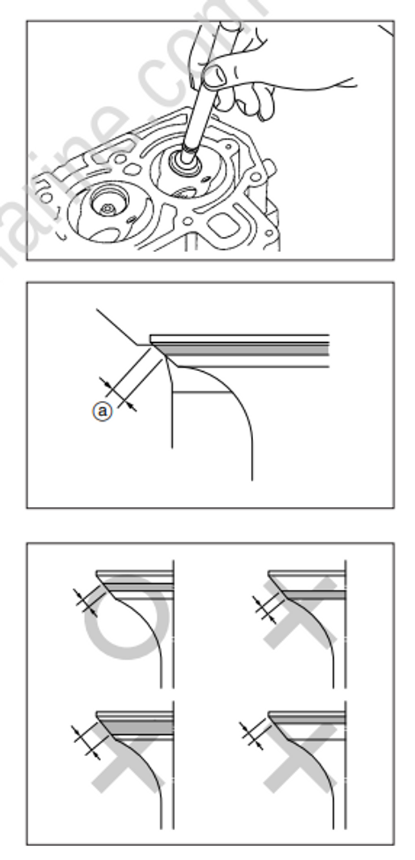
Use valve lapper (commercially available item) as shown to push valve onto valve seat lightly.
Measure width of area where valve face contacted with valve seat a that can be identified with red lead adhered to valve face. Correct valve seat if contact area is above or below the center or contact area of valve seat is over specified limit.
Valve Seat Contact Width (a) : Standard Value
Intake/Exhaust Side : 1.0 mm (0.04 in)
Functional Limit :
Intake/Exhaust Side : 2.0 mm (0.08 in)
Step 26: Correction of Valve Seat
- Use valve seat cutter (commercially available item) to correct valve seat.
Be careful not to over-cut valve seat. Turn valve seat cutter while pushing down evenly.
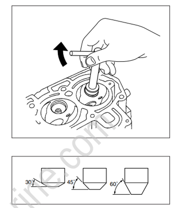
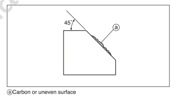
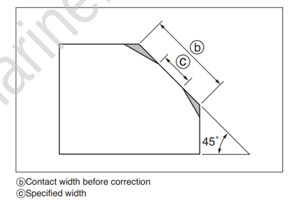
- Turn 45° degree cutter clockwise to cut valve seat surface to make it smooth.
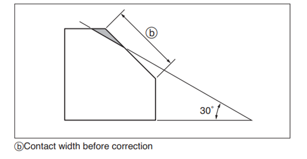
- Use 30° degree cutter to adjust contact position of valve seat upper end.
- Use 60° degree cutter to adjust contact position of valve seat lower end.
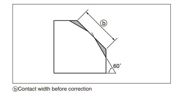
- Use 45° degree cutter to adjust contact width of valve seat (c) to specified value.
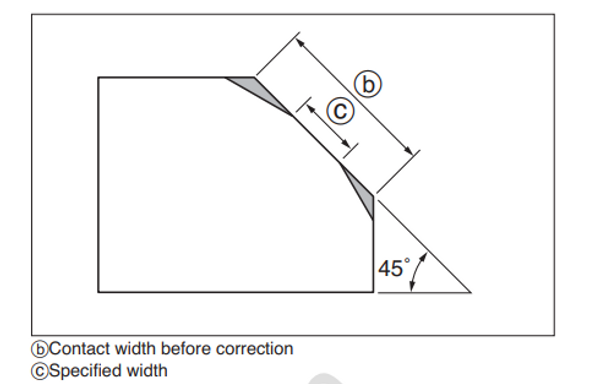
- Valve seat contact area is located on the center, which should be adjusted to specified value by cutting upper and lower ends by using 30° degree and 60° degree seat cutters respectively if the area is too wide.
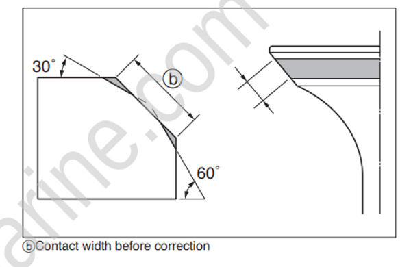
- If valve seat contact area is very narrow and is located nearer to valve face upper end, use 30° degree seat cutter to cut upper end. If necessary, use 45° degree cutter to adjust contact width of valve seat to specified value.
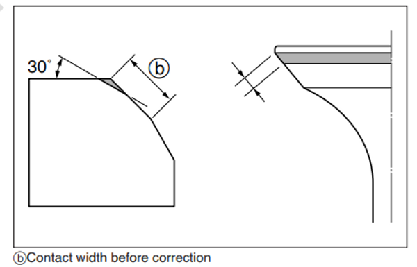
- If valve seat contact area is very narrow and is located nearer to valve face lower end, use 60° degree seat cutter to cut lower end. If necessary, use 45° degree cutter to adjust contact width of valve seat to specified value.
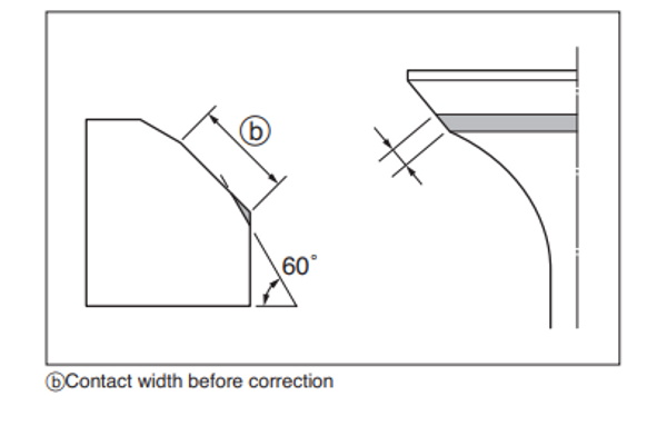
- Apply thin coat of abrasive compound on the overall valve seat contact area, and turn valve lapper (commercially available item) while lapping valve.
Perform the work by taking care not to allow abrasive compound to adhere to valve stem and valve guide.
Use finer abrasive compound to finish.
When changing abrasive compound to finer one, remove present one completely.
After completion of lapping, wipe off the compound and then clean.
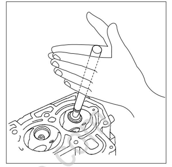
After ending the work, remove the compound completely from cylinder head and valve.
Check valve seat contact width (c).
Valve Seat Contact Width c : Standard Value
1.0 mm (0.04 in)
Step 27: Inspection of Rocker Arm and Rocker Arm Shaft
Check rocker arm, rocker arm shaft and rocker arm contact area (a) for wear. Replace if necessary.
Measure rocker arm inner diameter (b) and rocker arm shaft outer diameter (c). Calculate oil clearance (d) ((d) = (b) - (c)). Replace if out of specification.
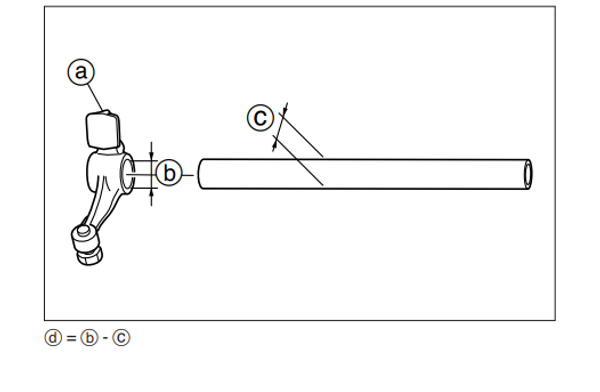
Rocker Arm Inner Diameter (b) : Standard Value
13.01 mm (0.5122 in)
Rocker Arm Shaft Outer Diameter (c) : Standard Value
12.99 mm (0.5114 in)
Oil Clearance Between Rocker Arm Hole and Shaft (d) :
0.006 - 0.035 mm (0.00024 - 0.00138 in)
Functional Limit :
(b) Replace if b is over 13.05 mm (0.5138 in).
(c) Replace if c is less than 12.94 mm (0.5094 in).
(d) Replace if b is over 0.060 mm (0.00236 in).
Step 28: Inspection of Cam Shaft
- Measure cam height. Replace if it is less than specified value.
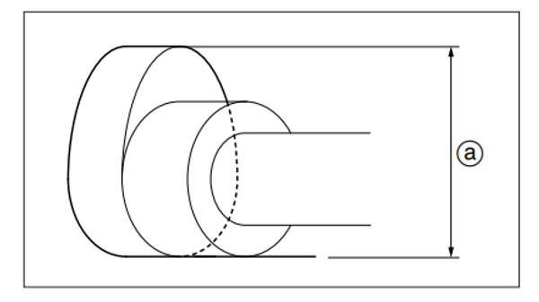
Cam Height (a) at Both Intake and Exhaust Side : Standard Value
23.63 mm (0.9303 in)
Functional Limit : Cam Height (a) at Both Intake and Exhaust Sides
23.38 mm (0.9205 in)
- Measure cam shaft journal outer diameters (c) and (d). Replace cam shaft or cylinder head if either of the diameters is less than specified value.
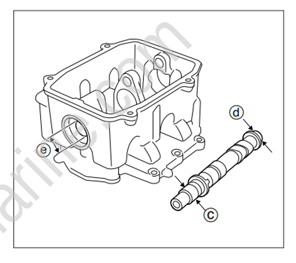
Cam Shaft Journal Outer Diameter (c) : Standard Value
17.98 mm (0.7079 in)
Cam Shaft Journal Outer Diameter (d) : Standard Value
15.97 mm (0.6287 in)
Cylinder Head Journal Inner Diameter (e) (Upper) :
18.010 - 18.025 mm (0.7091 - 0.7096 in)
Functional Limit (c) :
17.95 mm (0.7067 in)
Functional Limit (d) :
15.95 mm (0.6280 in)
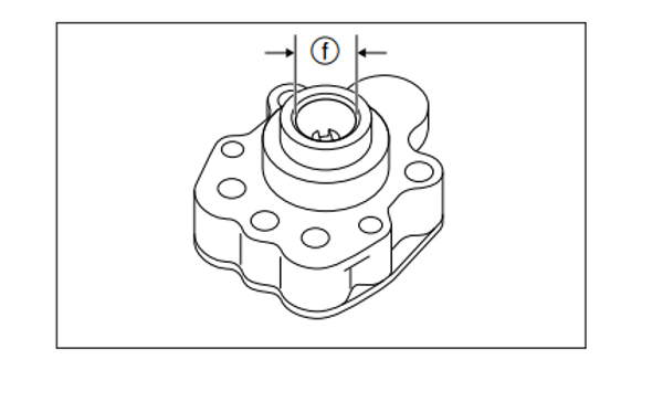
- Measure cylinder head journal inner diameter e and oil pump journal inner diameter f. Calculate oil clearance. Oil clearances are obtained by (e) - (c) and (f) - (d) respectively. Replace cam shaft, cylinder head or oil pump if either of the clearances is over specified value.
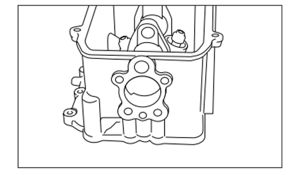
Oil Clearance : Standard Value
0.02 - 0.05 mm (0.0008 - 0.0020 in)
Functional Limit :
0.09 mm (0.0035 in)
If oil clearance is over functional limit, replace any of cylinder head, cam shaft and oil pump or all of them as a set, and check that the clearance is within specified range.
Step 29: Inspection of Cylinder Head
Remove carbon build-up of combustion chamber, and check for deterioration.
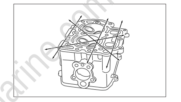
Use straight edge (1) and thickness gauge (2) to check distortion of cylinder head in the directions shown. Replace if the distortion is over specified value.
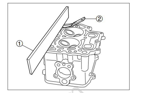
Cylinder Head Distortion Limit :
0.10 mm (0.004 in)
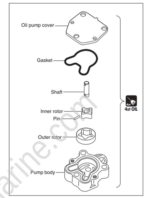
Step 30: Inspection of Oil Pump
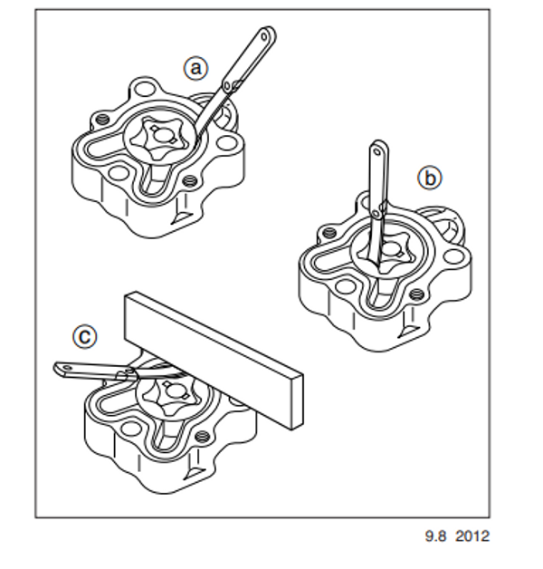
- Use micrometer, cylinder gauge, depth gauge and thickness gauge to measure dimensions shown below. Replace oil pump if over specified value.
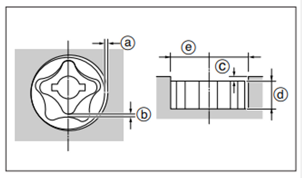
Functional Limit :
Clearance between Outer Rotor and Body (a) :
0.36 mm (0.0142 in)
Clearance between outer and inner rotors (b) :
0.16 mm (0.0063 in)
Side clearance between rotor and body (c) :
0.11 mm (0.0043 in) (including wear of oil pump cover)
Height of Outer Rotor (d) :
9.96 mm (0.3921 in)
Pump Body Inner Diameter (e) :
29.04 mm (1.1433in)
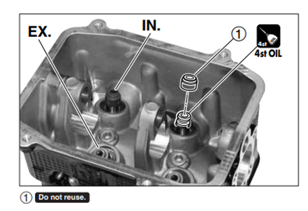
Step 31: Installation of Valves
- Apply oil to valve guide and attach new valve stem seal (1).
Intake Side : Black
Exhaust Side : Green
4st OIL
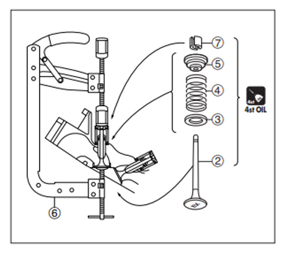
- Install valve (2), valve spring seat (3), valve spring (4) and retainer (5) in the order shown, and then, attach commercially available valve spring compressor (6).
Valves, springs and other power unit related parts should be arranged in the order they are removed.
Use attachment with inner diameter of 23.5mm.
If valve spring compressor is not used, put cylinder head on the folded rag to prevent valves from being damaged.
- With valve spring (4) being compressed, use small screw driver with small amount of grease at the tip to put cotter (7).
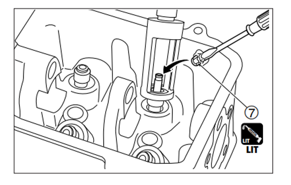
- Tap valve stem end with plastic hammer to fix cotter (7) securely.
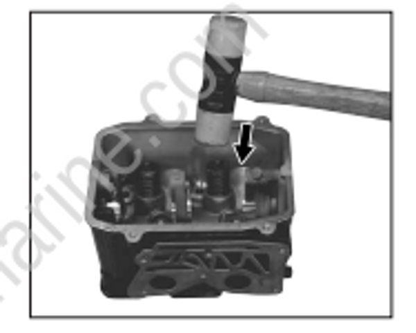
Step 32: Installation of Cam Shaft
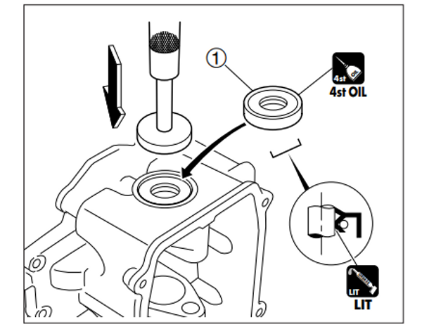
- Apply engine oil to periphery of new oil seal 1 and install it.
Driver Rod :
P/N. 5041762
Oil Seal Installer :
P/N. 5041763
Apply Lithium grease to lip of oil seal before installing it.
LIT
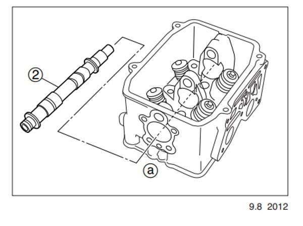
- Install cam shaft (2) from direction (a) shown.
Step 33: Installation of Rocker Arm Shaft
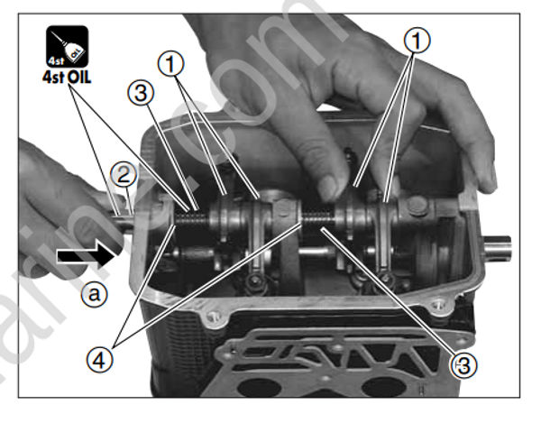
- Apply sufficient amount engine oil to cam surface of cam shaft and journal of rocker arm shaft.
4st OIL
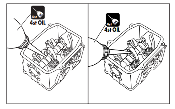
- Install rocker arms (1), springs (3), washers and collar (4) from lower side of cylinder head a while installing rocker arm shaft (2).
Apply sufficient amount of engine oil to rocker arm and adjust screw after installing rocker arm.
4st OIL
Step 34: Installation of Oil Pump
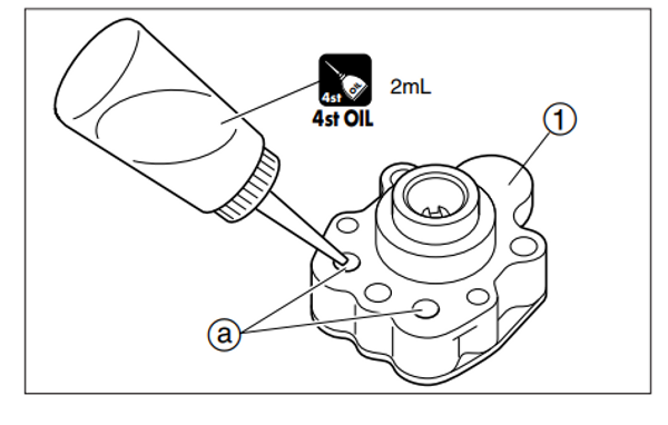
Feed engine oil of approximately 1mL to oil passages (a) before installing oil pump.
4st OIL
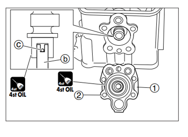
- Align cuts of oil pump drive shaft (b) and cam shaft pin (c) with each other to install oil pump (1).
Use new gasket (2).
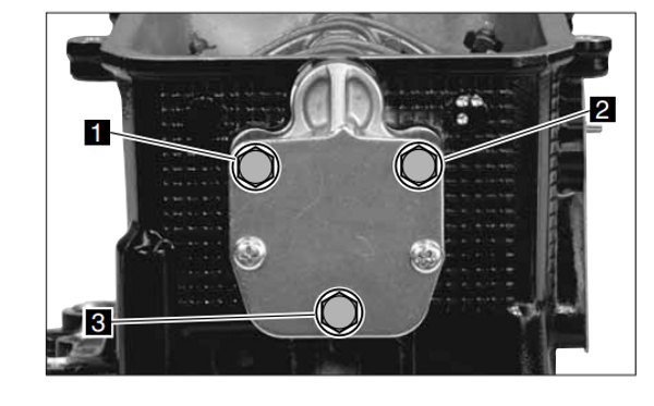
- Secure oil pump using three M6 bolts by tightening them to specified torque in the order specified below. Order of tightening : 1 → 2 → 3
Oil Pump Bolts :
First tightening torque : 4 N · m (3 lb · ft) [0.4 kg · m]
Second Tightening Torque : 9 N · m (7 lb · ft) [0.9 kg · m]
Step 35: Installation of Cylinder Head
Degrease mating surfaces of cylinder head and cylinder block.
No.1 piston is to be at top dead center of compression stroke.
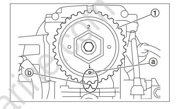
- After installing cam shaft pulley, bring "●1" mark (a) of pulley 1 to "▲" mark (b) of cylinder head.
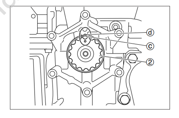
- Check that "▲" mark (c) of timing pulley 2 and "▲" mark (d) of cylinder block are aligned with each other.
No.1 piston is to be at top dead center.
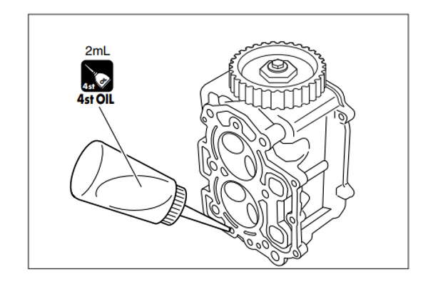
- Before installing cylinder head, fill oil passages and oil pump again with engine oil as shown.
4st OIL
- Install cylinder head with new gasket, and tighten bolts in the order shown in two steps to specified torque.
· Do not reuse cylinder head gasket. Be sure to replace with new one.
· Do not turn timing pulley or cam shaft pulley with timing belt removed. Doing so can make pistons and valves interfere with each other, possibly resulting in damages to these parts.
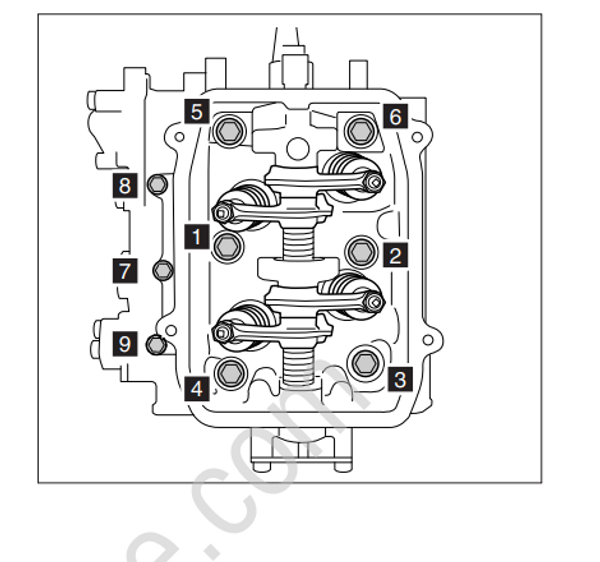
First, tighten M8 bolts in two steps to specified torque.
Then, tighten M6 bolts in two steps to specified torque.
After installing cylinder head, install timing belt and check valve clearance. Refer to “Chapter 5 Checking Valve Clearance".
Cylinder head bolts (M8) (1) to (6)
First Tightening Torque : 10 N · m (7 lb · ft) [1.0 kgf · m]
Second Tightening Torque : 30 N · m (22 lb · ft) [3.0 kgf · m]
Cylinder head bolts (M6) to
First Tightening Torque : 6 N · m (4 lb · ft) [0.6 kgf · m]
Second Tightening Torque : 10N · m (7 lb · ft) [1.0 kgf · m]
- Put new O ring and then cylinder head cover, and tighten bolts coated with Three Bond 1342.
1342
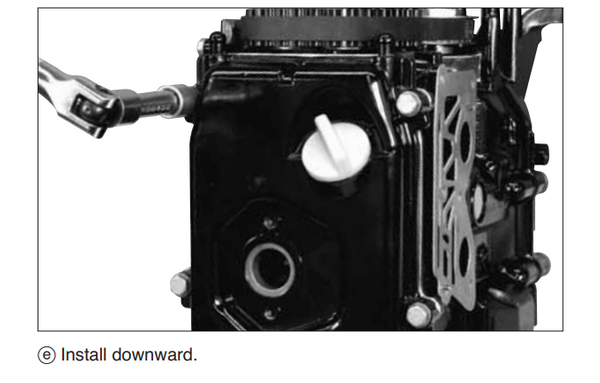
Step 36: Disassembly of Cylinder Block
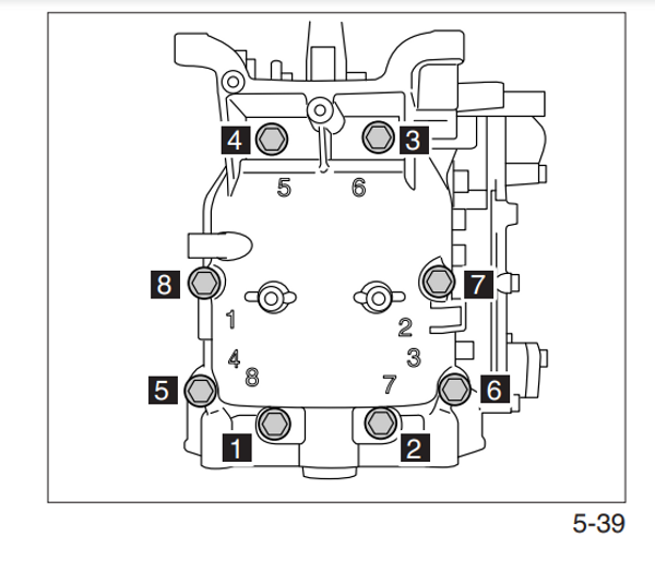
- Loosen crank case bolts in several steps in the reverse sequence of order shown, and remove crank case. (1) to (8).
Do not scratch or give damage to mating surfaces of crank case.
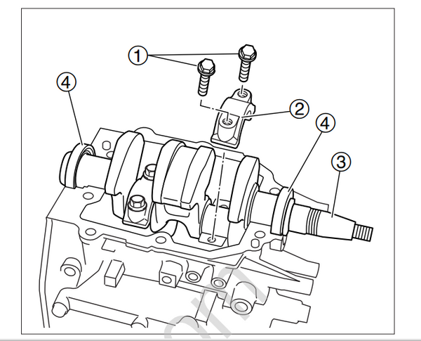
- Remove connecting rod bolts (1) and connecting rod cap (2), and then, crank shaft (3) and oil seal (4).
The mating connecting rods and caps should be arranged as pairs in the order they are removed. Removed parts should be marked and arranged so that they can be reassembled in their original positions and orientations.
Remove connecting rod and piston ass’y from cylinder block.
Remove bearings from cylinder block and crank case.
Take special care when reassembling connecting rod and connecting rod cap. Incorrect combination of the parts may
cause burn of big end.
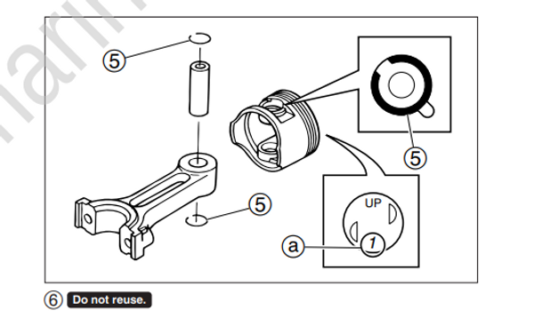
- Remove piston pin clips 5 and piston pin, and then, piston.
Write cylinder number a on the mating piston.
Do not reuse piston pin clips. Be sure to replace with new ones.
Step 37: 27) Inspection of Piston Outer Diameter
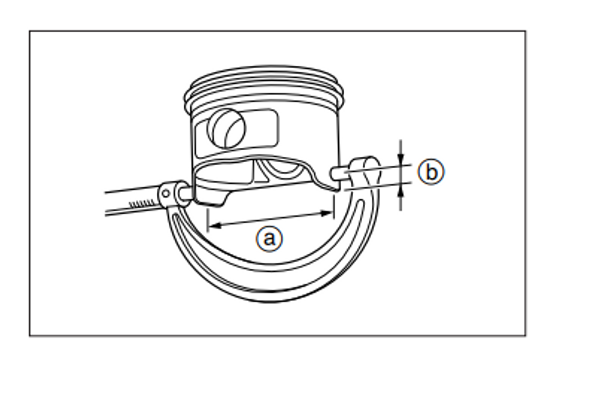
- Measure piston outer diameter between points specified. Replace if it is less than specified value.
Piston Outer Diameter (a) : Standard Value
54.96 mm (2.1638 in)
Measurement point b: on the line at right angle to piston pin.
7mm (0.28 in) above piston skirt bottom
Functional Limit :
54.90 mm (2.1614 in)
Step 38: Inspection of Cylinder Inner Diameter
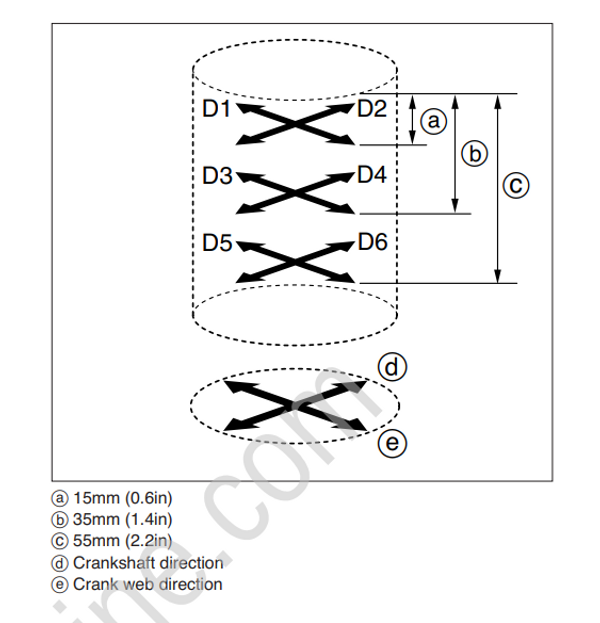
- Measure cylinder inner diameters (D1 to D6) at (a), (b) and (c) in crank shaft directions (d) (D1, D3 and D5 respectively), and in crank web directions e (D2, D4 and D6 respectively).
Cylinder Inner Diameters (D1 to D6) : Standard Value 55.00 mm (2.1654 in)
Functional Limit : 55.06 mm (2.1677 in)
Maximum value – Minimum value = 0.06mm
If serviceable limit is exceeded, replace, or bore to ø55.5 ± 0.01mm and hone, and replace pistons and piston rings with oversize parts.
Measure at the maximum wear points.
- Check inner surface of cylinders. If any flaw is found, remove by using sand paper in number 400 to 600 range.
If use of sand paper cannot remove the flaw, bore and hone, and use oversize pistons and piston rings.
Step 39: Inspection of Piston Clearance
- Obtain piston clearance through calculation described below. If piston clearance is over specified limit, replace cylinder block, or piston and piston rings as a set, or both cylinder block, piston and piston rings.
Piston clearance = Cylinder inner diameter
(maximum) - Piston outer diameter (a)
0.020 - 0.055 mm (0.00079 - 0.00217 in)
Step 40: Inspection of Piston Ring Side Clearance
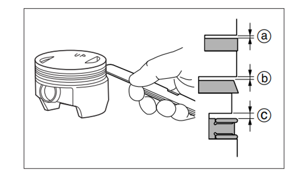
- Measure piston side clearance. Replace piston and piston rings as a set if the clearance is over specified value.
Piston Ring Side Clearance :
Top Ring a : 0.04 - 0.08mm (0.0016 - 0.0031 in)
Second Ring b : 0.03 - 0.07mm (0.0012 - 0.0028 in)
Oil Ring c : 0.05 - 0.15mm (0.0019 - 0.0059 in)
Functional Limit :
Top Ring a : 0.10 mm (0.0039 in)
Second Ring b : 0.09 mm (0.0035 in)
Oil Ring c : 0.18 mm (0.0071 in)
Step 41: Inspection of Piston Rings
1 Push piston ring (1) into ring gauge 55.000mm (2.1654in) parallel to top edge.
- When ring gauge is not available, use piston crown to push piston ring (1) into to cylinder.
Measure at the top or bottom of cylinder bore with no wear.
- Measure piston ring closed gap a. Replace if it is over specified value.
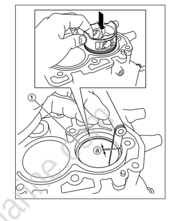
Piston Ring Closed Gap (a) :
Top Ring : 0.15 - 0.30 mm (0.0059 - 0.0118 in)
Second Ring : 0.35 - 0.45 mm (0.0138 - 0.0177 in)
Oil Ring : 0.20 - 0.70 mm (0.0079 - 0.0276 in)
Functional Limit :
Top Ring : 0.50 mm (0.0197 in)
Second Ring : 0.70 mm (0.0276 in)
Replace oil ring when top ring or second ring is replaced.
Step 42: 32) Inspection of Piston Pins
- Measure piston pin outer diameter. Replace piston pin if outer diameter is less than specified value.
Piston Pin Outer Diameter : Standard Value
14.00 mm (0.5512in)
Functional Limit :
13.97 mm (0.5500 in)
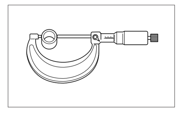
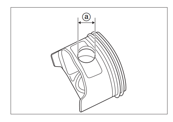
2 Measure piston pin boss inner diameter a, and calculate clearance between piston pin and pin hole. Replace piston pin or piston if the clearance is over specified value.
Clearance Between Piston Pin and Pin Boss :
0.002 - 0.012 mm (0.00008 - 0.00047 in)
Functional Limit :
0.040 mm (0.00157 in)
Step 43: Inspection of Connecting Rod Small End Inner Diameter
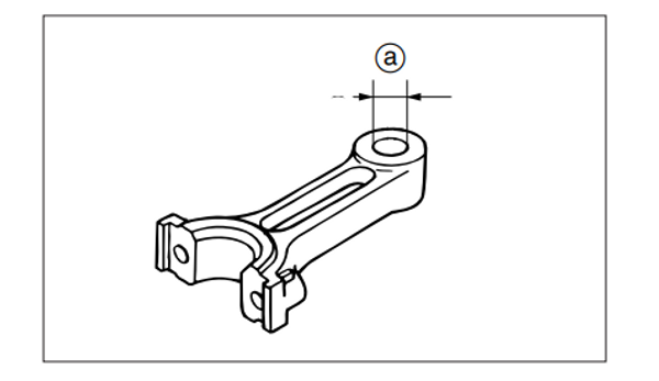
- Measure connecting rod small end inner diameter (a). Replace connecting rod if the diameter is over specified value.
Connecting Rod Small End Inner Diameter a : Standard Value
14.01 mm (0.5516 in)
Functional Limit :
14.04 mm (0.5526 in)
Step 44: Inspection of Connecting Rod Big End Side Clearance
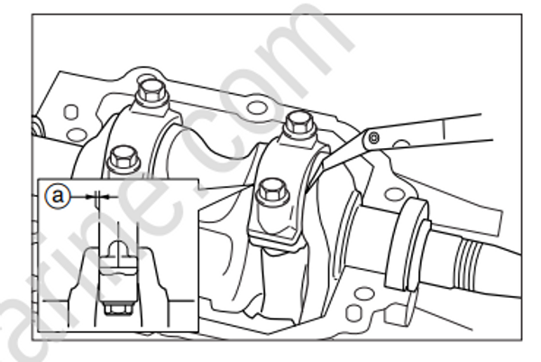
- Measure connecting rod big end side clearance a. Replace connecting rod and/or crank shaft if the clearance is over specified value.
Connecting Rod Big End Side Clearance a :
0.10 - 0.25 mm (0.0039 - 0.0098 in)
Functional Limit :
0.60 mm (0.0236 in)
Step 45: Inspection of Crank Shaft
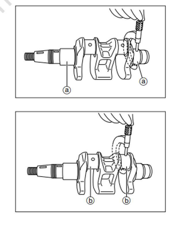
- Measure crankshaft journal outer diameter a and crank pin outer diameter b. Replace crankshaft if either outer diameter is less than specified value.
Crankshaft Journal Outer Diameter (a) : Standard Value
29.99 mm (1.1807 in)
Crank Pin Outer Diameter (b) : Standard Value
26.98mm (1.0622 in)
Functional Limit :
Crankshaft Journal Outer Diameter (a) :
Replace if less than 29.97 mm (1.1799 in).
Crank Pin Outer Diameter (b) :
Replace if less than 26.95mm (1.0610 in).
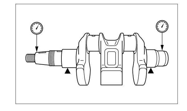
- Measure crankshaft runout. Replace crankshaft if runout is over specified value.
Crankshaft Runout Limit :
0.05 mm (0.0020 in)
- Use commercially available thickness gauge to measure side clearance.
Side Clearance :
0.10 - 0.30 mm (0.0039 - 0.0118 in)
Functional Limit :
0.6 mm (0.024 in)
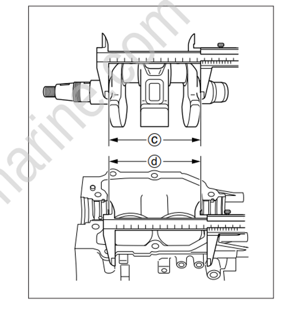
If side clearance is over specified value, measure crank case (cylinder side) width d and crankshaft width (c), and replace the part of which width is out of specified range.
Crankshaft Width (c) : Standard Value
117.8 - 117.9 mm (4.6378 - 4.617 in)
Crank Case Width (d) : Standard Value
118.0 - 118.1 mm (4.6457 - 4.6496 in)
Step 46: Inspection of Crank Pin Oil Clearance
Clean connecting rod.
Place cylinder block upside down on the work bench. Install piston to connecting rod (1), and install the assembly to cylinder block.
Piston rings are not to be attached to piston.
Install crankshaft on the cylinder block.
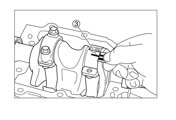
Place plasti-gauge (3) on each crank pin (4) parallel to crankshaft.
Do not place plasti-gauge (3) on the oil hole (5) of crank pin (4).
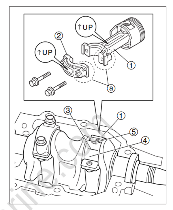
- Install connecting rod and cap (2) to crank pin (4).
Be sure that individual cap is installed to their original connecting rod.
Check that "UP" mark (b) of connecting rod is at crankshaft flywheel side (c)
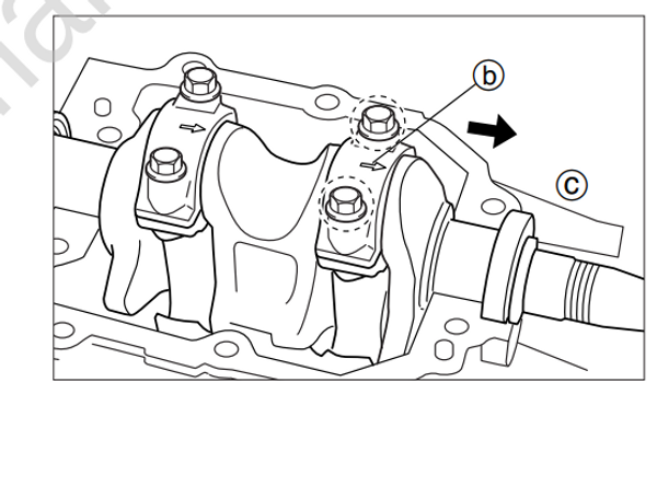
- Tighten connecting rod bolts in two steps to specified torque.
Do not move connecting rod and crankshaft until oil clearance measurement is completed.
Connecting Rod Bolts :
First Tightening Torque : 6 N · m (4 lb · ft) [0.6 kgf · m]
Second Tightening Torque : 12 N · m (9 lb · ft) [1.2 kgf · m]
- Remove connecting rod cap and measure width of crushed plasti-gauge (3) on each crank pin. Replace connecting rod or crankshaft if the width is over specified value.
Crank Pin Oil Clearance :
0.015 - 0.041 mm (0.00059 - 0.00161 in)
Functional Limit :
0.060 mm (0.00236 in)
Step 47: Inspection of Crankshaft Main Journal Oil clearance
Clean bearings, crankshaft main journal, and bearing installation areas of crank case and cylinder block.
Place cylinder block on the work bench with cylinder head side facing downward.
Install bearing (1) and crankshaft (2) to cylinder block (3).
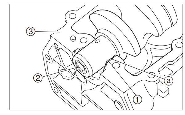
Be sure that individual bearings are installed to their original locations.
Install bearings with their projection a fit into cylinder block groove.
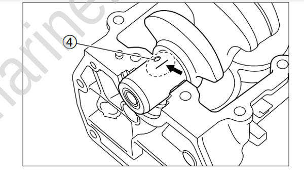
- Place plasti-gauge (4) on each crankshaft main journal parallel to crankshaft.
Do not place plasti-gauge (4) on the oil hole of crankshaft main journal.
- Install bearings to crank case.
Be sure that individual bearings are installed to their original locations.
Install bearings with their projection fit into crank case groove.
Install crank case to cylinder block.
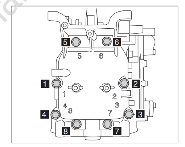
Tighten crankcase bolts in the order of numbers shown in two steps to specified torque.
Crank Case Bolts : (1) to (8)
First Tightening Torque : 10 N · m (7 lb · ft) [1.0 kgf · m]
Second Tightening Torque : 23.5 N · m (17 lb · ft) [2.4 kgf · m]
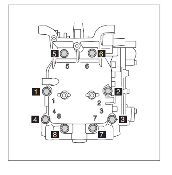
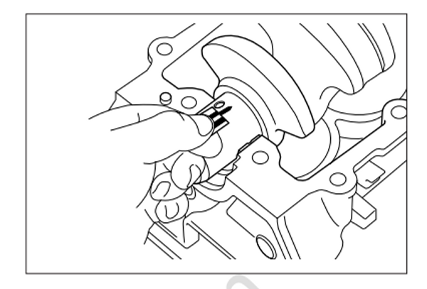
- Loosen bolts in reverse order in several steps. Remove crank case and measure width of crushed plasti-gauge on each main journal. Replace bearing if the width is over specified value.
Crankshaft Main Journal Oil Clearance :
0.012 - 0.044 mm (0.00047 - 0.00173 in)
Functional Limit :
0.060 mm (0.00236 in)
If the clearance is less than specified value, check that inner diameter code is as shown below.
Step 48: Inner Diameter of Cylinder/Crank Case Bearing Holder (Inner Diameter Code)
Cylinder is marked on its upper section with inner diameter code (1) that indicates inner diameter of each bearing holder.
There are the following two types of bearings that are indicated with the inner diameter code, which is to be used for identification of proper size part.
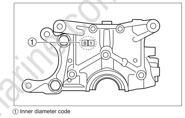
| Inner diameter code (1) | Standard value | Coloring of bearing |
|---|---|---|
| A or X | 33.000 - 33.008 mm (1.2992 - 1.2995 in) | Brown |
| B or Y | 33.008 - 33.016mm (1.2995 - 1.2998 in) | Black |
Inner diameter codes A and B or X and Y represent size of each bearing section.
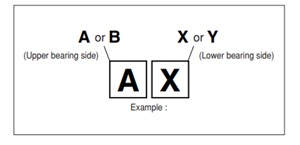
Remarks : When cylinder/crank case is purchased as a part, fitting bearing comes with it.
Step 49: Thickness of Metal Bearing (Color of Inner Diameter Code)
Bearing is painted with color a that represents thickness. There are the following two types of bearings that are to be selected properly.
| [Coloring (Inner Diameter Code)] | Thickness |
|---|---|
| Brown | 1.488 - 1.494 mm (0.05858 - 0.05882 in) |
| Black | 1.494 - 1.500 mm (0.05882 - 0.05906 in) |
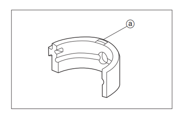
Step 50: Assembling Piston and Connecting Rod
- Install connecting rod (2), piston pin (3), and piston pin clip (4) to piston (1).
Point "3V1-UP" mark a of connecting rod and "UP" mark b of piston at the same direction.
Be sure to use new piston pin clip, and place clip gap away from piston pin groove (c) as shown.
Be sure that individual connecting rod cap is installed to their original connecting rod.

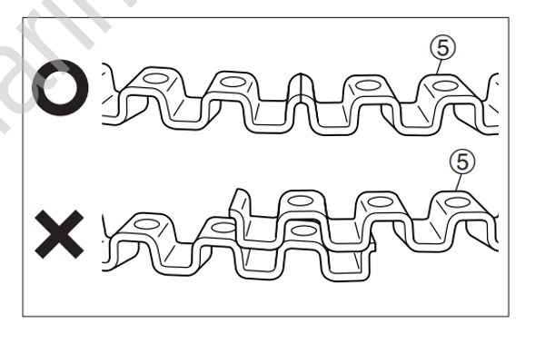
Put expander 5 (#4) into oil ring groove, and check that ring ends meet correctly as shown.
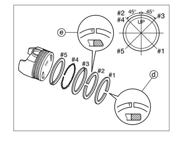
While holding expander (5) (#4) gap with thumb, put upper side rail (#3) end into the groove so that the gap is away from
gap of expander (5) (#4) to the left by 90° degrees.In similar way, put lower side rail (#5) into the groove so that the gap is away from gap of expander (5) (#4) to the right by 90° degrees.
Install second ring (#2 taper) and top ring (#1) to piston. Install the rings so that their side with manufacturer's identification de (T) faces upward.
Bring their gaps are away from each other as shown.
Be careful not to scratch piston surface and damage rings.
Install piston rings so that their gaps are away also from thrust direction of piston and direction piston pin.
After installing piston rings, check that they move smoothly
Step 51: Assembling Cylinder Block
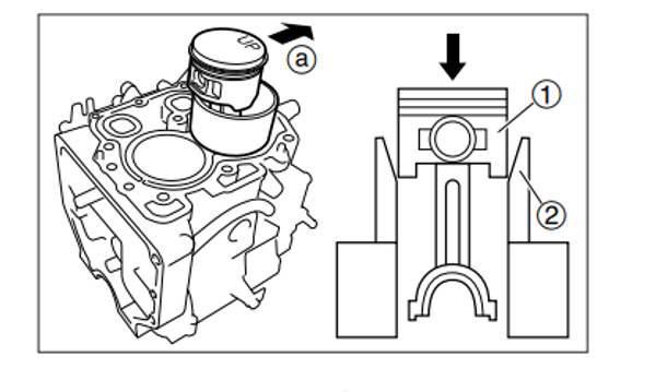
- Put pistons into cylinder with piston crown (1) "UP" mark directing flywheel side a, set pistons on the piston slider (2), install the piston into the cylinder.
Before installing, apply engine oil to piston peripheral surfaces, piston rings and piston sliders.
Piston Installer (2) :
P/N. 5041749
- Install bearing half (3) to cylinder block (4).
Be sure that individual bearings are installed to their original locations.
Install bearings with their projection b fit into cylinder block groove.
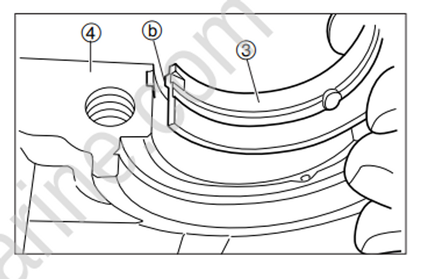
Apply engine oil to bearings and crankshaft, then install crankshaft.
Attach connecting rod cap 5 to connecting rod, and tighten connecting rod bolts 6 in two steps to specified torque.
- Bring each piston to bottom dead center position.
Be sure that individual connecting rod caps are installed to their original connecting rod.
Be careful of orientation of connecting rod cap.
After installing connecting rod cap, apply engine oil to connecting rod side clearance.
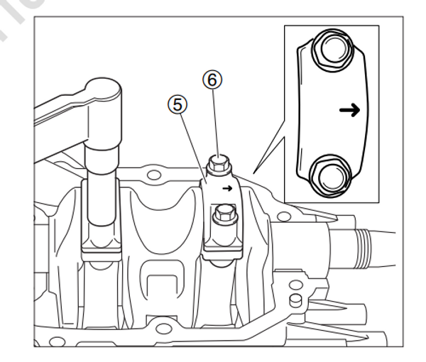
Connecting rod bolt (6) :
First Tightening Torque : 6 N · m (4 lb · ft) [0.6 kgf · m]
Second Tightening Torque : 12 N · m (9 lb · ft) [1.2 kgf · m]
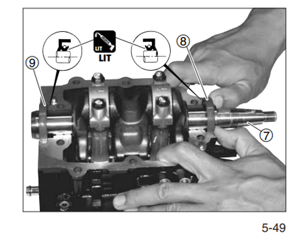
- Install oil seals (8) and (9) to crankshaft (7) as shown.
Apply Lithium grease to lip of oil seals before installing them.
LIT
- Install bearing half to crank case
Be sure that individual bearings are installed to their original locations.
Install bearings with their projection fit into crank case groove.
- Apply engine oil to bearings.
4st OIL
- Apply sealing agent to mating surface of crank case (one side).
Degrease mating surfaces of cylinder and crank case.
Be careful not to allow sealing agent to adhere to bearing.
Apply Loctite 518 to mating surface of one of crank case halves, taking care not to apply the agent excessively.
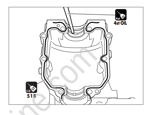
518
Install dowel pin and crank case on the cylinder block.
Tighten crank case bolts in two steps to specified torque in the order shown.
Crank Case Bolts :
First Tightening Torque : 10 N · m (7 lb · ft) [1.0 kgf · m]
Second Tightening Torque : 23.5 N · m (17 lb · ft) [2.4 kgf · m]
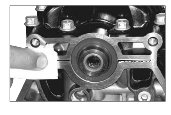
- Wipe off excess Loctite 518 from lower mating surface of crankcase.
Step 52: Assembling Power Unit
- Install exhaust cover (1), and then install thermostat (2), new gasket and thermostat cover (3).
For air bleeding, install the part with concave of valve facing upward.
When reusing thermostat, check the part by referring to Chapter 3.
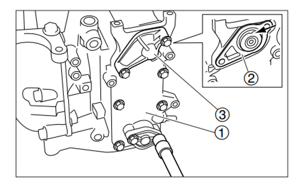
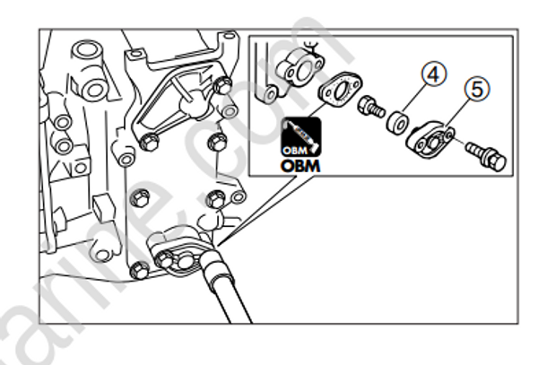
- Install new gasket, anode 4 and anode cap (5).
Apply thin coat gasket with grease before attaching it.
OBM
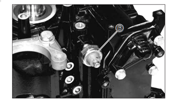
- Install oil pressure switch (6), and tighten to specified torque.
Before installing oil pressure switch, coat the thread with ThreeBond 1342.
Use socket wrench of which width between two parallel faces is 24mm.
Oil Pressure Switch:
8 N · m (6 lb · ft) [0.8 kgf · m]
1342
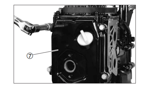
- Install cylinder head and cylinder head cover (7).
For installation procedure, refer to "Chapter 5 Installation of Cylinder Head".
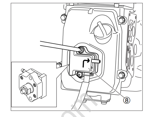
- Install fuel pump (8).
Apply engine oil to fuel pump cam surface.
- Attach timing belt to crankshaft pulley and cam shaft pulley.
For installation procedure, refer to "Installation of pulley and timing belt" in Chapter 5.
Ensure crankshaft rotates with no binding.
Step 53: Installation of Electrical Parts
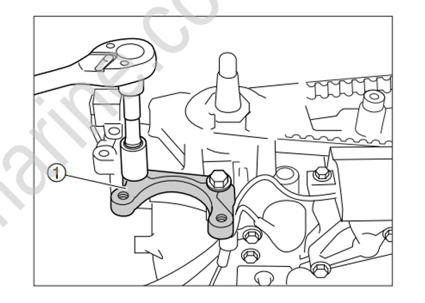
- Install starter motor bracket (1) and tighten bolts to specified torque. (E Model)
Install starter motor bracket with “UP” mark facing upward.
Before installing starter motor bracket, coat the bolts with ThreeBond 1342.
Starter Motor Bracket Installation Bolt :
23.5 N · m (17 lb · ft) [2.4 kgf · m]
1342
- Install alternator 2 and exciter coil (3).
Before alternator and exciter coil, coat the bolts with ThreeBond 1342.
1342
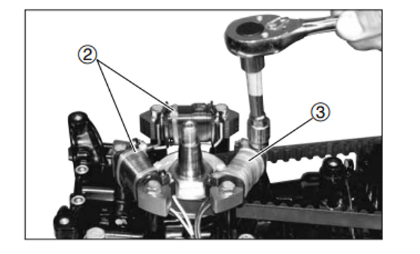
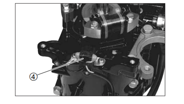
- Install pulser coil 4 on crank case
Use starboard side mounting screw for securing ground wire.
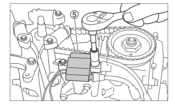
- Install ignition coil (5).
- Install CD unit bracket (6) and secure CD unit (7) using bolts.

- Install rectifier and attach ground wire from main harness.
(Other than MF model)
Use rectifier mounting bolt to secure ground wire.
Direct ground wire to stern side.
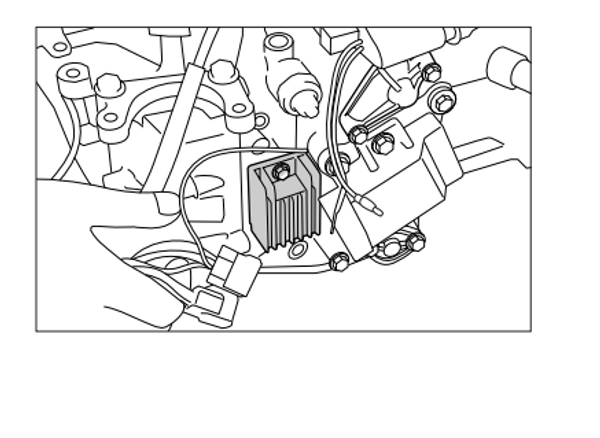
Connect main harness coupler to CD unit.
Attach sensor wire to oil pressure sensor, and install grommet (8).
When installing grommet, be careful not to plug small hole a of switch with grease.
Direct ground wire to Bow side.
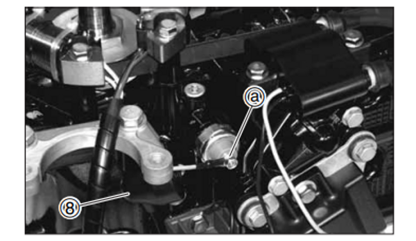
- Use clamp bolt to secure ground wire from ignition coil.
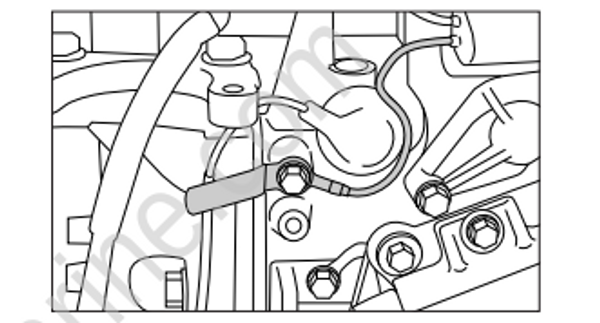
- Use crank case bolt to secure main harness ground wires (black and light green) and rectifier ground wire.
For MF model, use crank case bolt to secure only main harness ground wires (black and light green).
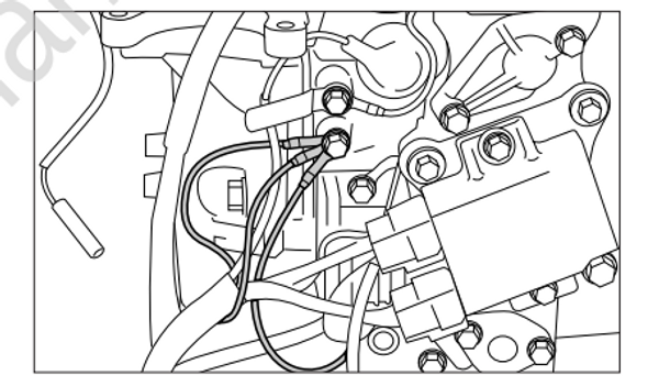
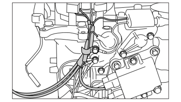
- Connect CD unit lead wire (orange) with ignition coil lead wire (orange), bundle the wires with sensor wire from oil pressure switch and cords from alternator, and secure them using clamp.
Step 54: Installation of Starter Motor (Electric start model)
- Attach starter cord to starter motor as shown, and then, terminal cap to starter cord.
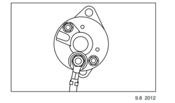
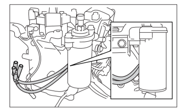
- Run two cords from alternator through back of starter motor, install starter motor and secure temporarily with bolts.
Install starter motor with sticker side directing toward you.
Before installing bolts, coat the thread with ThreeBond 1342.
Check that two cords from alternator are not caught between starter motor and crank case.
1342
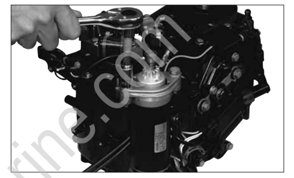
- Tighten temporarily secured bolts to specified torque.
Starter motor bolt :
23.5 N · m (17 lb · ft) [2.4 kgf · m]
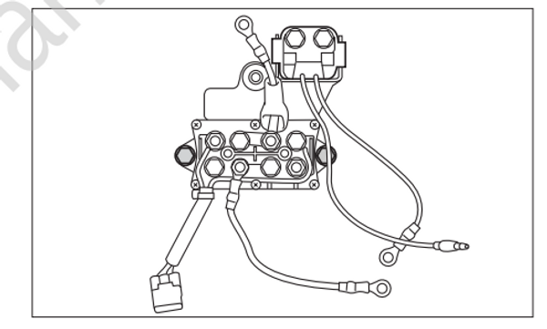
- Install starter solenoid and PT solenoid (PT model) to solenoid stay by using bolts and nuts.
Install PT solenoid in direction as shown.
- Install solenoid stay on crank case.
Install lower two bolts to the case with bushing.
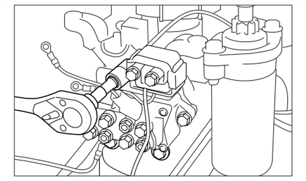
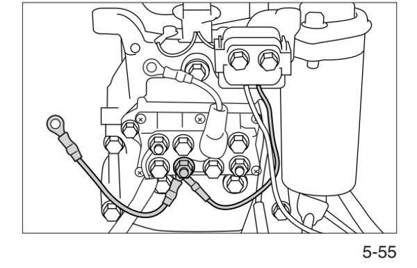
- Secure both ground lead from starter solenoid and ground cord together by using PT solenoid terminal (black). (PT Model)
Arrange ground wires as shown.
Step 55: Installation of Flywheel
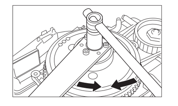
Install flywheel with flywheel engaged with crankshaft key.
Tighten flywheel nut to specified torque.
Flywheel Puller Kit
P/N. 5041743
Flywheel Nut :
55 N · m (40 lb · ft) [5.5 kgf · m]
Step 56: Installation of Recoil Starter
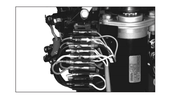
- Attach grommet to crank case, and then, install recoil starter, fuse holder, and cable terminal holder.
Use port side bolt to secure fuse holder and cable terminal holder.
Install fuse holder with hook face directed bow side.
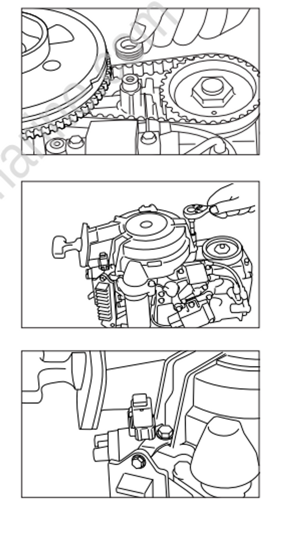
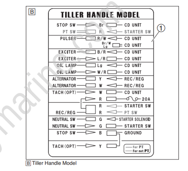
- Put cable terminal in the holder in accordance with description on the sticker (1) located on the back of holder cover.

Step 57: Installation of Intake Manifold
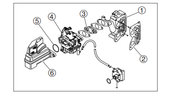
- Install gasket (2), insulator (3), carburetor (4), O ring (5) and intake silencer (6) to intake manifold (1) in this order and secure with bolts.
For EP model, put bracket for choke solenoid between carburetor (4) and intake silencer.
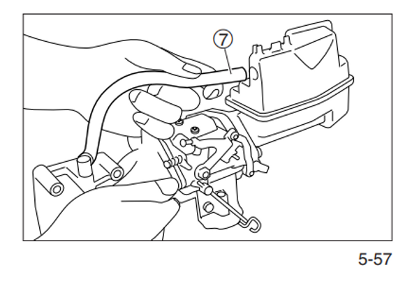
- Attach breather hose (7).
Put breather hose on the nipples of intake silencer and intake manifold.
- Install choke solenoid bracket ass’y (8) to intake manifold by using screws. (Remote Control Model)
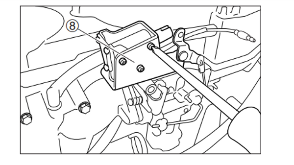
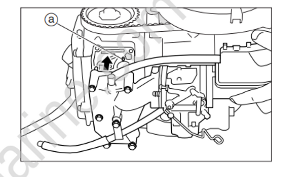
- Attach new gasket and intake manifold ass’y to cylinder block.
Use dowel pin a to locate intake manifold ass’y on the cylinder block.
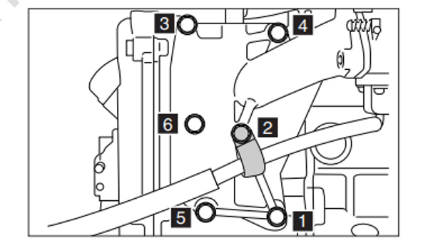
- Secure intake manifold ass’y by tightening bolts in the specified order to specified torque.
Use central bolt (2) to secure fuel hose holder.
Intake manifold ass’y mounting bolts :
First Tightening Torque : 4 N · m (3 lb · ft) [0.4 kgf · m]
Second Tightening Torque : 9 N · m (7 lb · ft) [0.9 kgf · m]
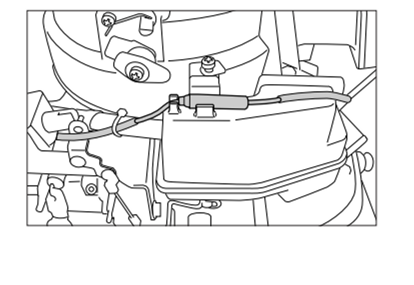
- Connect choke solenoid cord (blue) and cord (blue) to coupler, and put them in air intake silencer holder.
Step 58: Installation of Plunger and Oil Strainer
- With power unit and recoil starter attached, put power head ass’y (1) upside down on the work bench, and install plunger
(2) and oil strainer (3).
Complete this work in a short period. Doing this work for long time can cause engine oil to flow from breather pipe.
Plunger :
30 N · m (22 lb · ft) [3.0 kgf · m]
Step 59: Installation of Power Unit
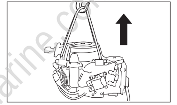
- Hoist power unit with rope as shown.
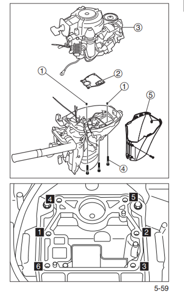
Clean surface of power unit that contacts with the engine base, and install dowel pin 1 and new gasket (2).
Install power unit (3), and tighten bolts (4) in two or three steps to specified torque.
Be careful not to catch wires and hoses and other parts between power unit and engine base.
Power Unit Installation Bolt :
First Tightening Torque : 12 N · m (9 lb · ft) [1.2 kgf · m]
Second Tightening Torque : 23.5 N · m (17 lb · ft) [2.4 kgf · m]
Attach drive shaft housing cover (5).
Install other parts by reversing the procedure described in “Chapter 5 Removing Power Unit”.
Step 60: Removing Recoil Starter Adjustment of Starter Lock Cable
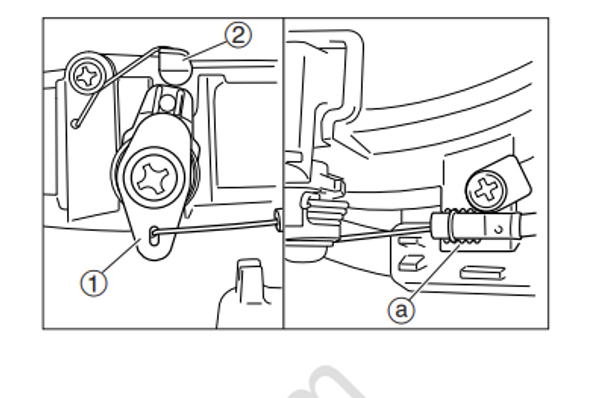
Shift gear into neutral (N).
Check that starter lock lever 1 pushes up starter lock (2).
If the state described in (2). does not exist, use starter lock wire adjusting groove a to adjust.
Perform shift operation to check that recoil starter is locked at other than neutral (N) position.
Step 61: Disassembly of Recoil Starter
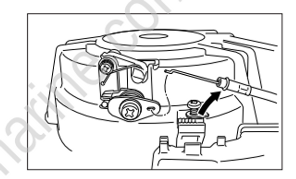
Loosen screw and disconnect starter lock cable (upper).
Remove bolts, and then, recoil starter.
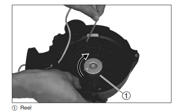
- Put rope in the groove of reel (1) and gently turn reel (1) clockwise to release tension of starter spring.
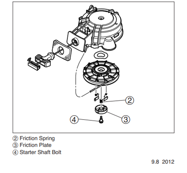
Remove starter shaft bolt (4), and then, friction plate (3), friction spring (2), ratchet, and return spring.
Take out reel carefully.
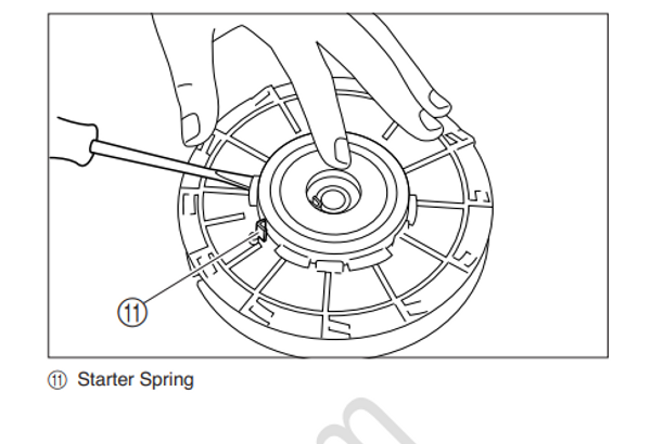
- Remove starter spring (11). Insert tool like bladed screw driver to remove starter case containing starter spring.
It is not necessary to remove starter spring from starter case if it is not necessary to replace it. Starter spring can be inspected without
removing from starter case.
Step 62: Inspection of Recoil Starter
Check ratchet, starter lock and all springs. Replace if any deformation, wear or damage is found.
Check reel and starter case. Replace if any crack or damage is found.
Check starter rope. Replace if any wear, unraveling or damage is found.
Step 63: 53) Assembling of Recoil Starter
Reverse disassembly procedure to assemble by taking care of the following matters.
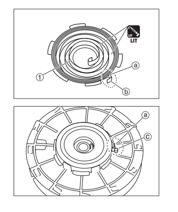
- When setting starter spring (1) into starter case, face starter spring outer edge hook a to the right and set it into peripheral cut (b) of starter case.
Since newly delivered starter spring is bound by wire, cut the wire to release the tension after setting outer end hook in the case.
When attaching starter spring and case to starter reel, align outer end hook a of starter spring with position of round projection (c) of starter reel.
Run starter rope through rope guide.
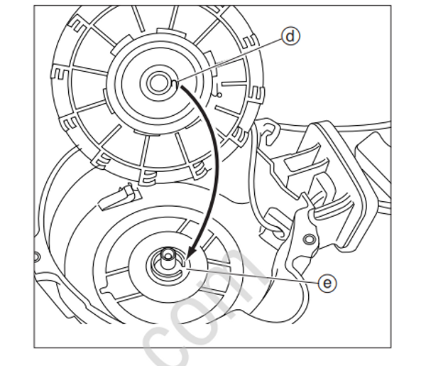
When attaching reel to starter case, put starter spring inner end hook d in the notch e of starter case bearing.
Apply cold resistance lithium grease to the following parts.
Starter Spring
Reel Center Hole
Ratchet
Starter Lock
Friction Plate
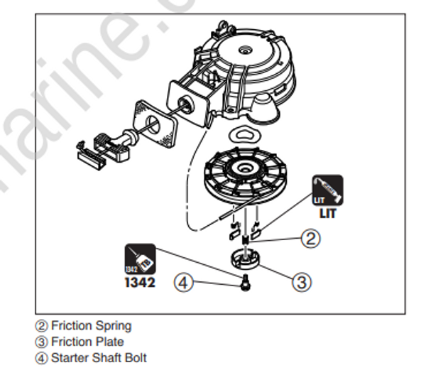
- Apply "Three Bond" 1342 to starter shaft bolt, and tighten the bold to specified torque.
Starter Shaft Bolt :
6 N · m (4 lb · ft) (0.6 kgf · m)
1342
LIT
When winding starter spring, turn reel 4 to 5 times to direction to which the reel rotates when pulling out starter rope (counterclockwise) . Then, set the spring so that the reel additionally turns 1/4 of a rotation to one rotation and 1/4 when the rope is fully pulled out. (approximately 5 to 6 rotations)
After installing recoil starter to outboard motor, perform shift operation to check that recoil starter is locked at other than neutral (N) position.