

Voltage Testing
Use the engine Monitor screen of the Evinrude Diagnostics Software program or a digital multi meter to check voltages. Identify all wiring and circuits prior to performing any voltage tests. Refer to Wiring Diagrams and descriptions of the various systems for specific information on each circuit.
Identify erratic or lower than expected voltage readings. Determine if the voltage source or the wiring and connections of the circuit are the problem.
IMPORTANT: Use a digital multi meter to per form voltage checks on external circuits only when necessary. All EMM output currents are DC current.
Battery Circuits (12 V)
Battery and auxiliary battery voltage is displayed on the engine Monitor screen of the diagnostic software. Each of these circuits are supplied approximately 25 A of battery charging current as needed and voltage is limited to approximately 14.5 V when outboard is running.
System Circuits (55 V)
55 V circuits are supplied 30 V when the key switch is ON, the EMM is powered up, and the outboard is not running and 55 V when outboard is running.
Stator output supplies the rectifier circuits of EMM with approximately 40 VAC when outboard is cranking and approximately 55 VAC when out board is running.
Ignition System Circuits
Ignition voltage displayed on the engine Monitor screen of the diagnostic software will have approximately 125 ± 10 V when the key switch is ON, the EMM is powered up, and the outboard is not running and 200 ± 10 V when outboard is running. Cranking voltage is approximately 200 V.
START CIRCUIT
The start circuit provides the required current to the starter motor and associated electrical circuits.
Electric Starter Operation
The starter must engage and turn the flywheel. A cranking speed of approximately 100 RPM must be achieved for the outboard to start. Normal cranking speed is approximately 175 RPM.
Optimum starter performance is achieved by providing:
- Proper battery capacity (675CCA). Refer TECHNICAL DATA on p. 18 for battery recommendations
• Cables capable of transferring the amperage
• Low resistance battery and cable connections
• A solenoid capable of switching the current
These “high amperage” start circuit components provide the battery current required to crank and start the outboard (electric start models). Check the quality and condition of the following:
12 V Marine Battery
• Battery type, capacity, and condition
• Condition of battery posts, terminals, and connections
• Battery switch type, capacity, and connections
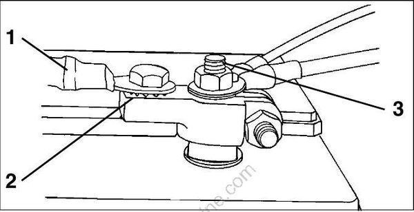
- Main battery cable
- Star washer
- Battery post
Refer to Battery Installation on p. 36 for battery, terminal, and cable requirements.
Starter Solenoid
- Starter solenoid and connections
- Starter solenoid switched ground (NEG), terminal “B”
- Starter cable (solenoid to starter motor)
- 12 V from solenoid terminal (POS) and engine harness (red wire) to 10 A fuse
Starter Motor and Drive Gear
• Starter motor operation, refer to ELECTRIC STARTER SERVICING on p. 156.
• Starter bendix operation.
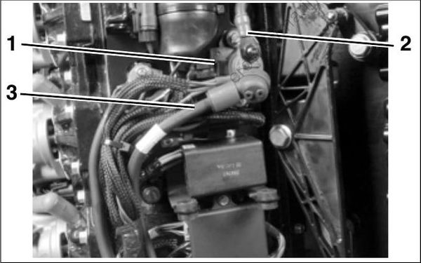
- Starter solenoid
- Starter cable
- POS battery cable
Starter Solenoid Activation
Solenoid Wiring
The positive (B+) battery cable connects to the large lower terminal of the starter solenoid. This terminal also provides the 12 V power supply to the engine harness (red wire) and the 10 A fuse. The red/purple wire from the fuse holder (10 A) provides 12 V to terminal “B” of key switch.The negative (B–) battery cable connects to the main ground stud at the electrical bracket.
Engine Wire Harness
Contains the following circuits:
- Red/purple output wire from fuse and provides 12 V to instrument harness
- Purple wire provides switched 12 V to solenoid (terminal “A”) and EMM
- Yellow/red wire provides switched 12 V to EMM
- Brown/white wire from terminal 11 of EMM J1-B connector provides switched ground (NEG) to starter solenoid (terminal “B”)
Instrument Wire Harness
Contains the following circuits:
- Red/purple wire provides 12 V to key switch terminal “B”
- Purple wire provides switched 12 V to engine wire harness
- Yellow/red wire from terminal “S” of key switch provides switched 12 V to EMM (key switch in START position)
Key Switch
Terminal “B” of key switch receives 12 V input from 10 A fuse.
IMPORTANT: Repeat failures of fuse could be the result of faulty connections or accessories. The 12 V accessory circuit (purple wire from terminal “A” of key switch) is often used to power gauges.
Key Switch, ON position
12 V is applied to the “accessory” circuit. Key switch ON:
- Switches 12 V to terminal “A” of key switch and to the purple wires of the wire harnesses.
- Provides 12 V input to terminal 21 of J1-B EMM connector and terminal “A” of starter solenoid.
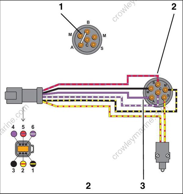
- Key switch, ON position – Continuity between terminals “B” and “A”
- Terminal “B”, 12 V (Red/purple)
- Terminal “A”, 12 V (Purple)
Key Switch, START Position
Switches 12 V to terminal “S” of key switch and 12 V is applied to neutral safety switch.
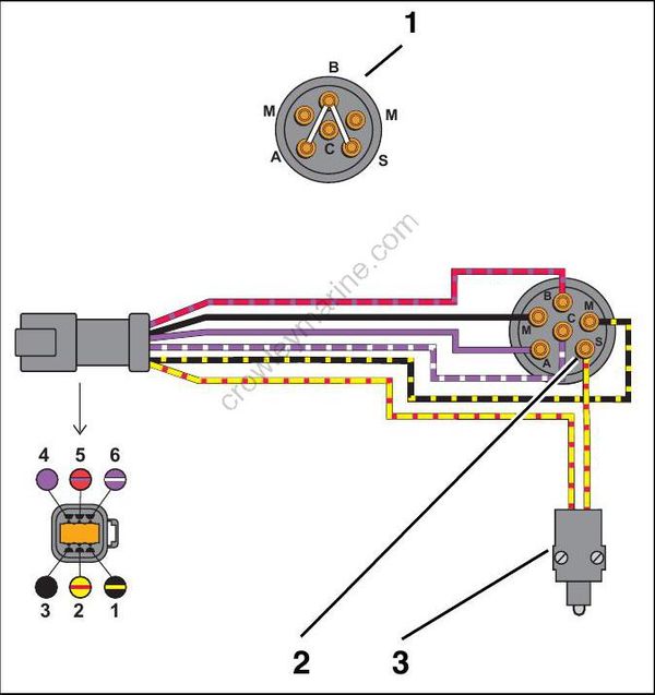
- Ignition switch, START position – Continuity
between terminals “B” and “A”; “B” and “S” - Terminal “S”, 12 V
- Neutral safety switch
Neutral Safety Switch (Remote Control)
Terminal “S” of the key switch provides 12 V (yellow/red) to the neutral safety switch (key switch in START position).
A depressed or activated neutral safety switch (in remote control) provides 12 V to the engine wire harness yellow/red wire (key switch in START position) and terminal 26 of EMM J-1A connector.
Start Circuit Diagram

- Marine battery
- RED wire (POS)
- BLACK wire (NEG)
- Starter solenoid
- Fuse (10 amp)
- RED/PURPLE wire
- 6-pin connectors
- Ignition switch
- PURPLE wire (switched B+)
- 26-pin J1-B EMM connector
- 34-pin J1-A EMM connector
- Engine Management Module (EMM)
- YELLOW/RED wire, start
- BROWN/WHITE wire, start signal
- Neutral Safety Switch (remote control)
- RED starter motor cable
- Electric starter motor
