

Emergency Stop Switch Test
This switch can be incorporated into the key switch or installed as a separate switch. Either style effectively connects the “M” terminals of the key switch.
The emergency stop switch function grounds the stop circuit wire (black/yellow) when the lanyard clip is removed. One “M” terminal is the ground wire (black) and one “M” terminal is the stop circuit wire (black/yellow).
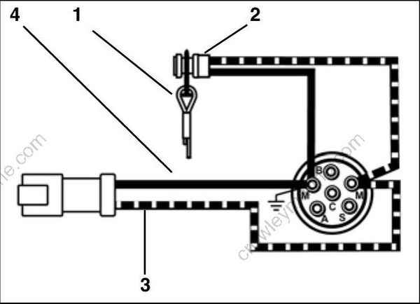
Lanyard and clip assembly
Emergency stop switch, separate from key switch
Stop circuit wire (black/yellow)
Ground wire (black)
Install the clip on the emergency stop switch or key switch. Start the outboard. Pull the clip from the switch. The outboard must stop running.
TACHOMETER CIRCUIT TESTS
Check voltage at the battery. Use this reading as a reference for battery voltage.

Purple lead
Black lead
Gray lead
STEP 1
Connect the red meter lead to the tachometer purple wire and the black meter lead to the tachometer black wire (key ON, outboard NOT running).
If meter shows battery voltage, go to STEP 2.
If meter shows less than battery voltage, check the purple, red/purple, and black wiring circuits, fuse, key switch, and battery connections.
STEP 2
Disconnect gray and black wires at tachometer. Set Fluke 29 Series II meter, or equivalent, to Hz scale. Connect meter between gray wire and black wire. With outboard running at 1000 RPM, meter should indicate 90 to 105 Hz.
If meter reads 90 to 105 Hz, replace tachometer.
If meter reads low or no signal, confirm output on gray wire at pin 16 of EMM J1-A connector.
– Reading OK – Check condition of tachometer circuit (gray wire). Repair as needed.
– Reading not OK – Check connection at EMM; replace faulty EMM.
