

Starter Solenoid Test
Disconnect the B+ (POS) battery cable at the battery.
IMPORTANT: Disconnect all wiring from solenoid terminals before proceeding with this test. Use an ohmmeter to measure resistance.
STEP 1
Put one ohmmeter lead on the starter positive (+) cable terminal and the other ohmmeter lead on the battery positive (+) cable terminal:
Ohmmeter must not show continuity (high reading).
If ohmmeter shows continuity (low reading), replace the solenoid.

“A” terminal, B+ (purple)
“B” terminal, NEG (brown/white)
Starter positive (+) cable terminal
Battery positive cable (B+) terminal
STEP 2
Apply B+ to terminal “A” of solenoid and ground (NEG) to terminal “B” of solenoid. Measure resistance between the starter positive (+) cable terminal and the positive battery (+) cable terminal.
The solenoid must close with an audible click.
Ohmmeter must show continuity (low reading).
If ohmmeter shows no continuity (high reading), replace the solenoid.
After re-installing the solenoid, coat all wires and terminals with Black Neoprene Dip.
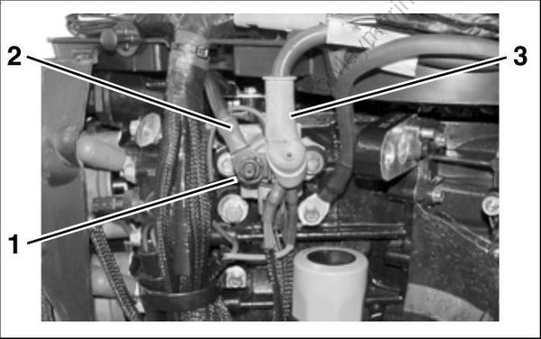
Starter solenoid
Starter cable
POS battery cable
No Load Current Draw Test
Securely fasten starter in a vise or suitable fixture before proceeding with this check.
Use a battery rated at 500 CCA (60 amp-hr) or higher that is in good condition and fully charged.
IMPORTANT: The driven gear and pinion assembly must be removed for this test.
Use an inductive ammeter or connect a 0 to 100 amp ammeter in series with a heavy jumper between the battery positive (+) terminal and the starter positive (+) terminal.
Fluke model 334 or 336, Snap-On model MT110 or EETA501, and various other ammeters should be available through local tool suppliers.
Attach or hold a vibration tachometer, such as a Frahm † Reed tachometer, to the starter.
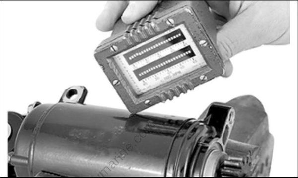
TYPICAL
Complete the circuit with a heavy jumper between the battery negative (–) terminal and the starter frame.
Monitor the starter RPM and current draw.
- At 10,500 RPM the ammeter should show a maximum of 30 A.
TILT/TRIM RELAY TEST
The tilt and trim (TNT) module contains the cir cuitry and relays required for power trim and tilt operation.
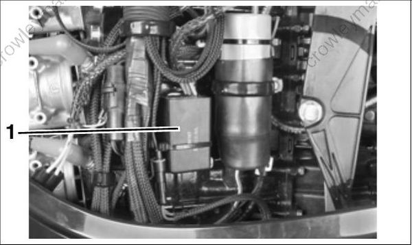
- Tilt and trim module
The tilt and trim switch provides B+ input to green/white or blue/white wire of the TNT module.
Operation
The relay activates when B+ input from the switch is supplied to terminal 86 of the internal relays.
Terminal 87a connects to ground (B–).
Terminal 87 connects to B+.
Terminal 30 connects TNT motor.
Terminals 87a and 30 are connected when relay is not activated. This supplies ground (B–) connection to TNT motor.
Terminals 87 and 30 are considered “normally open.” B+ is applied to terminal 30 when relay is activated. This supplies ground B+ connection to TNT motor.
Refer to Tilt and Trim Module Diagram.
