

EMM LED INDICATORS
The EMM LED indicators provide a quick reference to the status of several outboard systems.
Checking the LEDs FIRST when diagnosing an engine problem can save time.
LED 1 is closest to the center of the EMM (closest to EMM J1-A connector).

- LED indicators
- LED 1
Key ON
Diagnostic communications on non-running rope start models requires that power is supplied to the EMM. Refer to Communication on p. 88
When the EMM is ON (engine not running), the following LEDs should light:
LED 3 – Sensor Circuits working. FLASHING LIGHT indicates Code 57 – engine will not start.
LED 4 – Stop Circuit not grounded–okay to start. FLASHING LIGHT indicates severe overheat or no oil – engine in SHUTDOWN mode.
Starting
Starting mode occurs from the time the flywheel begins to turn until the outboard is running for 2 seconds. During starting, all four LEDs should light and then go off in sequence.
LED 1 – CHARGING OKAY – Stator signal 30 V or higher.
LED 2 – CRANK POSITION OKAY – input from CPS, EMM powered ON. For NO LIGHT, check for:
- Code 16 – CPS, intermittent loss of sync
LED 3 – SENSORS OKAY (5 V). For NO LIGHT, check for:
- Code 12 – TPS circuit fault
- Code 13 – TPS below expected range
- Code 14 – TPS above expected range
- Code 19 – In Gear (tiller models)
- Code 23 – EMM temp. sensor circuit fault
- Code 24 – EMM temp. below expected range
- Code 41 – temp. sensor circuit fault
- Code 42 – temp. below expected range
- Code 47 – AT sensor circuit fault
- Code 48 – AT sensor below expected range
- Code 49 – AT sensor above expected range
- Code 58 – Operating temperature not reached For FLASHING LIGHT, check for Code 57.
LED 4 – LANYARD/STOP OKAY. For NO LIGHT, check for:
- Grounded stop circuit.
For FLASHING LIGHT, check for:
- Code 29 – EMM temp. OVER range (flashing)
- Code 31 – Engine temp. OVER range (flashing)
- Code 33 – Engine shutdown, excessive no oil condition
Running
When the outboard is running, all of the LEDs should be off. If a light is on, check for:
LED 1 – CHARGING FAULT:
- Code 17 – system voltage (55 V) below range
- Code 18 – system voltage (55 V) above range
- Code 26 – low battery (12 V) voltage
- Code 27 – high battery (12 V) voltage *
LED 2 – INJECTOR/IGNITION FAULT:
- Code 51 – cylinder no. 1 injector circuit open
- Code 52 – cylinder no. 2 injector circuit open
- Code 61 – cylinder no. 1 injector circuit short
- Code 62 – cylinder no. 2 injector circuit short
- Code 81 – no. 1 ignition primary circuit open
- Code 82 – no. 2 ignition primary circuit open
- Code 91 – fuel pump open circuit
- Code 94 – fuel pump circuit short
- Code 101 – cylinder no. 1 igniton circuit short
- Code 102 – cylinder no. 2 igniton circuit short
LED 3 – Sensor circuits (5 V), SENSOR FAULT. For LIGHT ON, check for possible fault codes:
- Code 12 – TPS circuit fault
- Code 13 – TPS below expected range
- Code 14 – TPS above expected range
- Code 16 – CPS, intermittent loss of sync
- Code 23 – EMM temp. sensor circuit fault
- Code 24 – EMM temp. below expected range
- Code 41 – temp. sensor circuit fault
- Code 42 – temp. below expected range
- Code 47 – AT sensor circuit fault
- Code 48 – AT sensor below expected range
- Code 49 – AT sensor above expected range
- Code 57 – high RPM with low TPS setting
- Code 58 – operating temp. not reached
LED 4 – Engine overheat, EMM temperature or sensor, oil injection pump or sensor, NO OIL / OVERHEAT. For LIGHT ON, check for possible fault codes:
- Code 25 – EMM overheat
- Code 29 – EMM overheat, critical (flashing)
- Code 31 – engine overheat, critical (flashing)
- Code 33 – excessive NO OIL faults
- Code 34 – oil injection pump circuit open
- Code 40 – engine temp over range, low speed
- Code 43 – temp. above expected range
- Code 117 – Critical NO OIL detected
- Code 120 – Low Oil Switch circuit OPEN
IGNITION OUTPUT TESTS
The electrical system presents a serious shock hazard. Allow outboard to sit for two minutes after running before handling
DO NOT handle primary or secondary ignition components while outboard is running or flywheel is turning.
Use the Evinrude Diagnostics software Stored Faults screen to check for current service codes before troubleshooting. Correct any problems and clear the codes FIRST.
Required Ignition Systems
Following is a complete list of circuits required for ignition output:
Stop Circuit
- Black/yellow wire NOT grounded (emergency stop switch lanyard in place).
Neutral Switch (Tiller models only)
- Powerhead mounted neutral switch provides a switched ground circuit to EMM. The circuit enables specialized control functions such as neutral start protection and RPM limiting in NEUTRAL.
Stator Output Voltage
- Provides A/C voltage to EMM J1A connector: Outboard cranking, typical range is 20-40 VAC (AC output voltage is related to cranking RPM); Outboard running, approximately 55 VAC.
EMM
- Controls ignition grounds, injector grounds, and engine timing.
Crankshaft Position Sensor
- Provides EMM with input.
- Outboard cranking speed exceeds 300 RPM and a steady CPS signal is generated.
Alternator Output/System Voltage
- System voltage from EMM (white/red) provides 55 VDC to the high pressure fuel pump, the oil injection pump, the fuel injectors, and the ignition coils.
Ignition Coil
- Primary circuits are powered by system (55 V) voltage
- EMM provides control signal to ignition coil
- Output from ignition coil secondary winding and high tension spark plug wire.
Wiring Inspection
Visually inspect all wiring, connections, and grounds.
Use an ohmmeter to test resistance on all ground circuits and connections. Ohmmeter readings should be approximately 0.0 Ω.
Check that all engine wire harness grounds have continuity to the cylinder/crankcase.
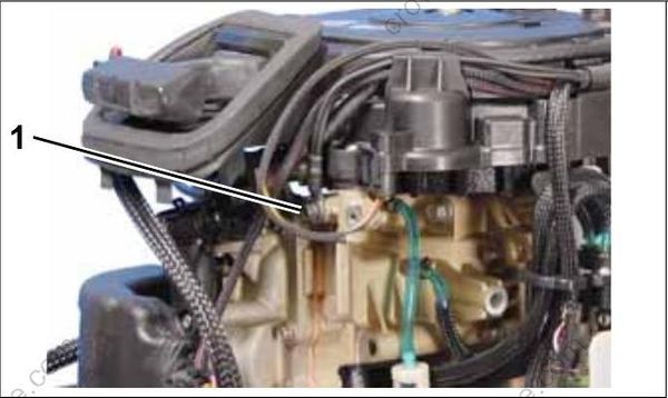
- Main engine harness ground
Clean or repair all ground circuits, wiring, and connections as needed.
