

OIL COMPONENT SERVICING
To prevent accidental starting while servicing, disconnect the battery cables at the battery.
Oil Distribution Hoses
Oil distribution hoses are different lengths. DO NOT alter the length of any hoses.
Oil Distribution Hose Length:
- Cylinder – 20 in. (508 mm)
- Crankcase – 10.5 in. (267 mm)
Removal
Release the hose by depressing the outer ring of the hose retaining mechanism.
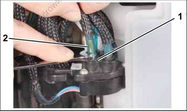
- Retainer mechanism
- Hose support
Once hose is removed from the manifold, make sure hose support is in the end of the hose.
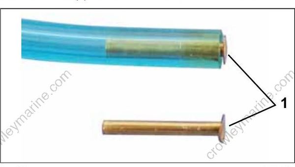
- Hose support
Installation
Cut Replacement Oil Hose, P/N 778708, to the correct length. Insert hose support in manifold end of hose.
DO NOT reinsert the hose into manifold without the hose support.
Be sure the hose is fully inserted into manifold. Insertion depth is 5/8 in. (16 mm). Visually inspect for hose supports.
Oil Distribution Manifold and Hose Retainer
Oil distribution hoses have specific locations and routing. DO NOT alter the location of any hoses. The oil distribution manifold includes a built-in hose retainer. Route oil distribution hoses up through the retainer.
Crankcase Oil Supply
Install crankcase oil distribution hoses to the forward oil manifold ports.
Install cylinder #1 oil hose to the inner (closest to powerhead) oil manifold port.
Install cylinder #2 oil hose to the outer (furthest from powerhead) oil manifold port.
Cylinder Block Oil Supply
Loop the cylinder block oil distribution hose over the crankcase oil distribution hose and install to the rear oil manifold port.
Install cylinder #1 oil distribution hose to the inboard (closest to powerhead) oil manifold port.
Install cylinder #2 oil distribution hose to the outboard (furthest from powerhead) oil manifold port.
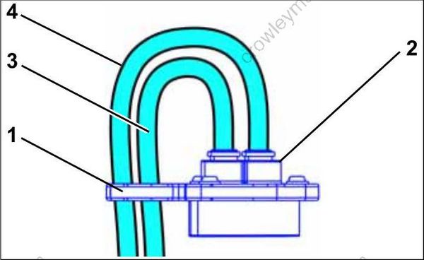
- Hose retainer
- Oil distribution manifold
- Crankcase oil supply hose
- Cylinder block oil supply hose
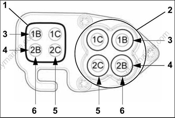
- Hose retainer
- Oil distribution manifold
- #1 Cylinder
- #2 Cylinder
- Crankcase
- Cylinder block
Refer to OIL SUPPLY DIAGRAMS on p. 171.
Oil Tank Assembly
Removal
Disconnect the battery cables at the battery.
Disconnect the electrical connector to the oil injection pump.
Disconnect the electrical connector to the low oil switch.
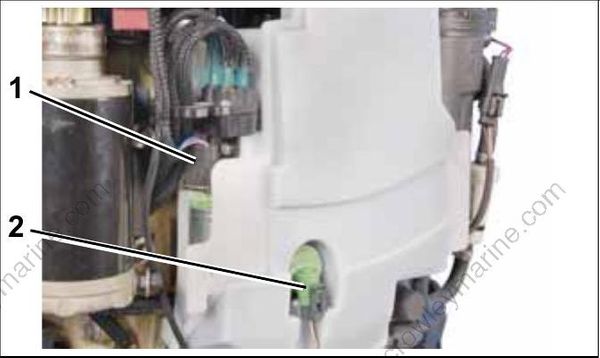
- Oil pump connector
- Low oil switch
Note oil distribution hose routings before proceeding with disassembly.
Remove oil distribution hoses from the crankcase fittings.
Remove oil tank retaining screw.
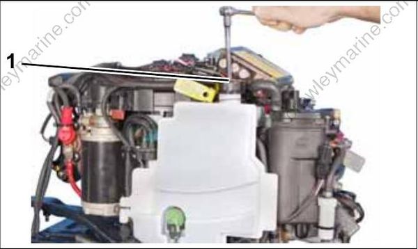
- Screw
Installation
Align grommets with pins on powerhead. Install oil tank assembly on powerhead. Clean mounting screw and apply Nut to threads. Install screws and tighten to a torque of 30 to 42 in. lbs. (3.5 to 5 N-m).
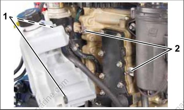
- Grommets
- Pins
Install protective sleeves and route oil distribution hoses from the oil distribution manifold to the crankcase and cylinder block oil delivery fittings. Refer to OIL SUPPLY DIAGRAMS on p. 171. Secure oil hoses to crankcase and cylinder block fittings with tie straps. On rope start models, install J-clamp to retain two crankcase oil supply hoses.
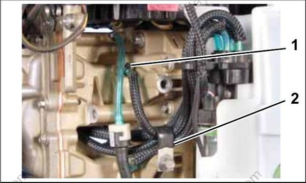
- Tie strap
- Clamp
Run outboard and check for leaks. Use Evinrude Diagnostics software to activate “Oil Prime.” Check oil flow through oil distribution hoses. Check oil system operation and routing of oil system hoses.
Repair any oil leaks and kinked or misrouted hoses. Install engine covers.
Oil Injection Pump
Removal
Remove oil distribution hoses from oil manifold. Refer to Oil Distribution Hoses on p. 180. Remove oil from oil tank.
Remove oil tank. Refer to Oil Tank Assembly on p. 181. Remove retaining screw from oil pump assembly. Twist and pull up on oil pump to remove from tank.
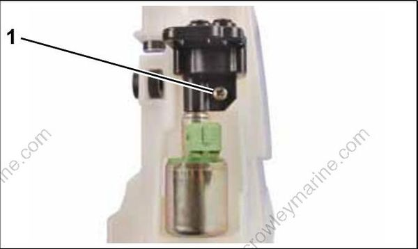
- Screw
Installation
Apply a drop of outboard lubricant to a new oil pump o-ring. Install o-ring on oil pump flange.
Installation is the reverse of removal.
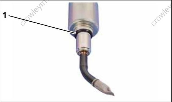
- O-ring
Install oil pump retainer screw. Tighten securely.
Turn self-tapping screws counter clockwise to start the threads and clockwise to tighten. Failure to follow this procedure can damage the threads of the oil tank.
