

Start Circuit Diagram
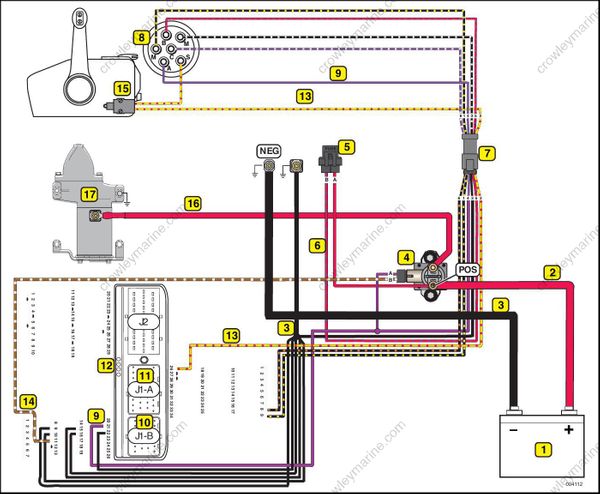
- Marine battery
- RED wire (POS)
- BLACK wire (NEG)
- Starter solenoid
- Fuse (10 amp)
- RED/PURPLE wire
- 6-pin connectors
- Ignition switch
- PURPLE wire (switched B+)
- 26-pin J1-B EMM connector
- 34-pin J1-A EMM connector
- Engine Management Module (EMM)
- YELLOW/RED wire, start
- BROWN/WHITE wire, start signal
- Neutral Safety Switch (remote control)
- RED starter motor cable
- Electric starter motor
Start Circuit Operation
The starter must engage and turn the flywheel. The outboard must crank a minimum of 100 RPM to start. Normal cranking speed is approximately 175 RPM.
Starter performance depends on the following:
Proper battery and cable capacity.
Clean, tight cable connections.
Solenoid activation through the key switch, neutral safety switch, and EMM.
Refer to Battery Installation on p. 29 for battery, terminal, and cable requirements.
Solenoid Wiring
The positive (B+) battery cable connects to a large terminal of the starter solenoid. This terminal also provides the 12 V power supply to the engine harness (red wire) and the 10 A fuse. The red/purple wire from the fuse holder (10 A) provides 12 V to terminal “B” of key switch.
The negative (B–) battery cable connects to the main ground stud next to starter solenoid.
Engine Wire Harness
Contains the following circuits:
Red/purple output wire from fuse provides 12 V to instrument harness.
Purple wire provides switched 12 V to solenoid (terminal “A”) and EMM.
Yellow/red wire provides switched 12 V to EMM.
Brown/white wire from terminal 11 of EMM J1-B connector provides switched ground (NEG) to starter solenoid (terminal “B”).
Instrument Wire Harness
Contains the following circuits:
Red/purple wire provides 12 V to key switch ter minal “B”.
Purple wire provides switched 12 V to engine wire harness.
Yellow/red wire from terminal “S” of key switch provides switched 12 V to EMM (key switch in START position).
Key Switch, ON position
12 V is applied to the accessory circuit. Key switch ON:
Switches 12 V to terminal “A” of key switch and to the purple wires of the wire harnesses.
Provides 12 V input to terminal 21 of EMM J1-B connector. EMM turns ON.
EMM provides 12 V to terminal “A” of starter solenoid.
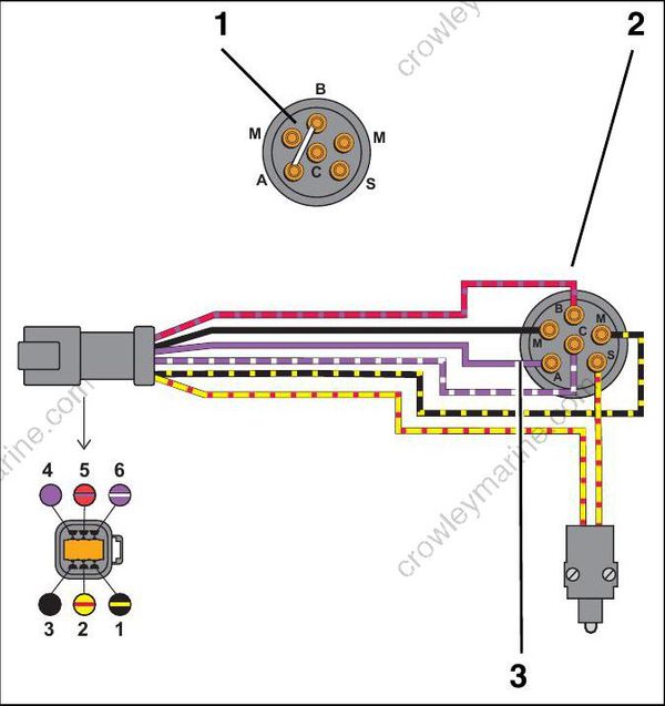
- Key switch, ON position – Continuity between terminals “B” and “A”
- Terminal “B”, 12 V (Red/purple)
- Terminal “A”, 12 V (Purple)
Key Switch, START Position
Key switch START:
Switches 12 V to terminal “S” of key switch and to the neutral safety switch (in remote control).
A closed neutral safety switch provides 12 V to the engine wire harness yellow/red wire and terminal 26 of EMM J-1A connector.
EMM grounds brown/white wire to activate solenoid.
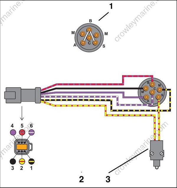
- Ignition switch, START position – Continuity between terminals “B” and “A”; “B” and “S”
- Terminal “S”, 12 V
- Neutral safety switch
ELECTRIC START TESTS
Starter Solenoid Test
Disconnect the B+ (POS) battery cable at the battery.
IMPORTANT: Disconnect all wiring from solenoid terminals before proceeding with this test.
Use a digital multimeter to measure resistance.
Put one meter lead on the starter positive (+) cable terminal and the other lead on the battery positive (+) cable terminal:
Meter must not show continuity (high reading).
If meter shows continuity (low reading), replace the solenoid.
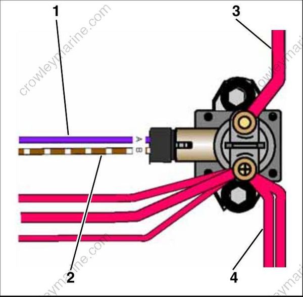
- “A” terminal, B+ (purple)
- “B” terminal, NEG (brown/white)
- Starter positive (+) cable terminal
- Battery positive cable (B+) terminal
Apply B+ to terminal “A” of solenoid and ground (NEG) to terminal “B” of solenoid. Measure resistance between the starter positive (+) cable terminal and the positive battery (+) cable terminal.
The solenoid must close with an audible click.
Meter must show continuity (low reading).
If meter shows no continuity (high reading), replace the solenoid.
