

ELECTRICAL HARNESS CONNECTIONS
Inspect wiring and electrical connections. Disassemble and clean all corroded connections. Replace damaged wiring, connectors, or terminals. Repair any shorted electrical circuits. Refer to wiring diagrams and reference charts for specific wiring details.
Refer to CONNECTOR SERVICING on p. 156.
Engine Harness to Stator Connector
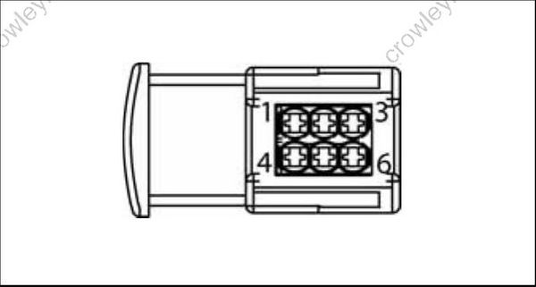
| Pin No. | Description of Circuit | Wire Color |
|---|---|---|
| 1 | Stator winding (1S) | Yellow |
| 2 | Stator winding (3S) | Orange |
| 3 | Stator winding (2S) | Brown |
| 4 | Stator winding (1F) | Yellow /White |
| 5 | Stator winding (3F) | Orange/White |
| 6 | Stator winding (2F) | Brown/White |
EMM J1-A Connector
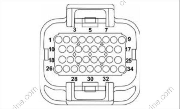
| Pin No. | Description of Circuit | Wire Color |
|---|---|---|
| 1 | Oil Pressure sensor | Tan/White |
| 2 | Diagnostic connector | Red |
| 3 | Diagnostic connector | White |
| 4 | Ground, water in fuel (digital) | Black |
| 5 | Oil level switch | Tan/Black |
| 6 | Crankshaft position sensor (CPS) | Yellow |
| 7 | Ground, CPS (digital) | White |
| 8 | Bootstrap connector (programming) | Blk/Orange |
| 9 | Stop circuit | Blk/Yellow |
| 10 | Throttle position sensor (TPS) 5 V | Red |
| 11 | Ground (analog) | Black |
| 12 | Engine temperature sensor, port | Pink/Black |
| 13 | CANbus, NET-L | Blue |
| 14 | CANbus, NET-H | White |
| 15 | Water pressure | Pink |
| 16 | Tachometer | Gray |
| 17 | CHECK ENGINE signal, SystemCheck | Tan/Orange |
| 18 | TPS | Green |
| 19 | Engine temperature sensor, starboard | Pink/Black |
| 20 | Air temperature sensor | Pink/Blue |
| 21 | CANbus, NET-S | Red |
| 22 | CANbus, NET-C | Black |
| 23 | Water in fuel | Pink/Green |
| 24 | NO OIL signal, SystemCheck | Tan/Yellow |
| 25 | WATER TEMP signal, SystemCheck | Tan |
| 26 | Start signal | Yellow/Red |
| 27 | vacant | |
| 28 | vacant | |
| 29 | Shift switch (shift linkage) | Black/Yellow |
| 30 | Trim relay, UP | Blue/White |
| 31 | Trim relay, DOWN | Green/White |
| 32 | Trim sender, IN | White/Tan |
| 33 | Trim sender, OUT | White/Tan |
| 34 | LOW OIL signal, SystemCheck | Tan/Black |
EMM J1-B Connector
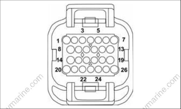
| Pin No. | Description of Circuit | Wire Color |
|---|---|---|
| 1 | Injector, cylinder 1 | Blue |
| 2 | Injector, cylinder 2 | Blue |
| 3 | Injector, cylinder 3 | Purple |
| 4 | +55V, in, (ignition) | White/Red |
| 5 | Fuel pump | Red/White |
| 6 | Ignition, cylinder 4 | Orange/Purple |
| 7 | Ignition, cylinder 3 | Orange/Purple |
| 8 | Injector, cylinder 6 | Green V6 |
| 9 | Injector ground | Black |
| 10 | Injector ground | Black |
| 11 | Starter solenoid OUT | Brown/White |
| 12 | vacant | |
| 13 | Ignition, cylinder 5 | Orange/Green V6 |
| 14 | Injector, cylinder 5 | Green V6 |
| 15 | Injector ground | Black |
| 16 | Injector ground | Black |
| 17 | Ignition ground | Black |
| 18 | Ignition ground | Black |
| 19 | Ignition, cylinder 2 | Orange/Blue |
| 20 | Injector, cylinder 4 | Purple |
| 21 | Switched B+ (12V) | Purple |
| 22 | Injector ground | Black |
| 23 | Oil solenoid | Blue |
| 24 | Ignition ground | Black |
| 25 | Ignition, cylinder 6 (none V4) | Orange/Green V6 |
| 26 | Ignition, cylinder 1 | Orange/Blue |
EMM J2 Connector
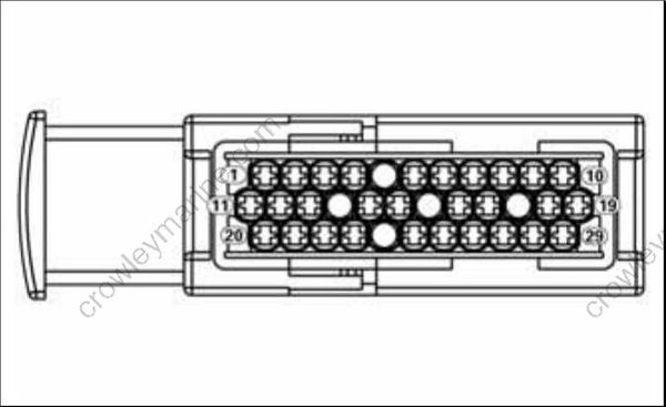
| Pin No. | Description of Circuit | Wire Color |
|---|---|---|
| 1 | B+ | Red |
| 2 | none | N/A |
| 3 | Isolated B+ | Red/Black |
| 4 | Battery ground | Black |
| 5 | Battery ground | Black |
| 6 | none | N/A |
| 7 | Winding 1S | Yellow |
| 8 | Winding 2S | Brown |
| 9 | Injector, generator ground | Black |
| 10 | Winding 3S | Orange |
| 11 | B+ | Red |
| 12 | B+ | Red |
| 13 | Isolated B+ | Red/Black |
| 14 | Battery ground | Black |
| 15 | Battery ground | Black |
| 16 | Battery ground | Black |
| 17 | Winding 1F | Yellow/White |
| 18 | Winding 3F | Orange/White |
| 19 | +55V | White/Red |
| 20 | B+ | Red |
| 21 | Isolated B+ | Red/Black |
| 22 | Isolated B+ | Red/Black |
| 23 | Battery ground | Black |
| 24 | Battery ground | Black |
| 25 | Battery ground | Black |
| 26 | none | N/A |
| 27 | Injector, generator ground | Black |
| 28 | Winding 2F | Brown/White |
| 29 | +55V | White/Red |
