

Step 1: OIL SYSTEM REQUIREMENTS
Recommended Lubricants
Evinrude/Johnson XD100, XD50, or XD30 out board oils are recommended for use in Evinrude E-TEC outboards. If these oils are not available, you must use a TC-W3 certified oil.
Evinrude/Johnson XD100 outboard oil is highly recommended for all conditions and applications.
Engine Lubricant Below 32°F (0°C)
If the outboard will be operated in temperatures below freezing (32°F, 0°C), use Evinrude/Johnson XD100.
IMPORTANT: For new outboards, test low oil warning before filling oil tank.
Turn key switch to ON. The engine monitor warning display should show “LOW OIL.”
Add enough oil to raise level to at least one-quarter capacity.
The “LOW OIL” warning should not display.
Failure to follow these recommendations could void the outboard warranty if a lubrication-related failure occurs.
Step 2: COMPONENTS
The oiling system includes the following components:
- Oil tank
- Oil injection pump and manifold assembly
- Electrical circuit
- LOW OIL and NO OIL warning systems
- Cylinder and crankcase
- Oil recirculation system.
Oil Tank Assembly
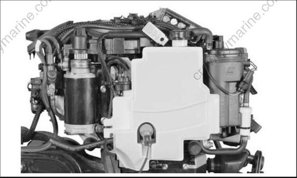
The oil tank is mounted on the powerhead under the engine cover. Oil level must be monitored.
Oil Tank Components:
- Tank, 1.5 quarts. (1.4 liter) capacity
- Oil pickup and filter assembly
- Oil injection pump and manifold assembly
- LOW OIL switch
- Oil distribution hoses
Oil Injection Pump
The oil injection pump is an electric (55 V) actuator style pump. It draws oil from the oil tank and supplies pressurized oil to the oil manifold. The EMM supplies 55 V and controls activation of the pump.
The oil manifold distributes the oil supplied by the pump.
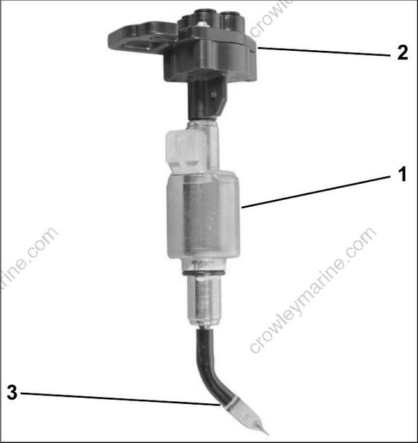
- Oil injector pump
- Oil distribution manifold
- Pickup tube and filter
Electrical Circuit (55 V)
The oil injector is powered by the 55 V electrical circuit. The EMM controls pump operation by rap idly connecting and disconnecting the pump’s internal coil to ground.
The EMM monitors the oil injection pump electrical circuit. If circuit voltage is beyond the specified range, or the circuit is open, the EMM:
| Activates S.A.F.E |
| Stores a service code 34 |
| EMM LED 4: ON (Running) |
| Engine Monitor LOW OIL display: ON |
LOW OIL Warning
A switch in the oil tank assembly monitors the oil level in the oil tank.
If the oil level falls below one-quarter capacity, the EMM begins counting oil pump pulse cycles. When it reaches 1000 pulses, the EMM signals:
Engine Monitor LOW OIL display: ON
Approximate oil reserve at Low Oil activation:
- 0.375 qt. (0.35 l).
NO OIL Warning
After LOW OIL is displayed, the EMM counts oil pump pulse cycles again. When it reaches 6700 pulses, the EMM:
| Activates S.A.F.E |
| Stores service code 117 |
| EMM LED 4: ON (Running) |
| Engine Monitor LOW OIL display: ON |
To recover from S.A.F.E. mode:
- Oil level must be above one-quarter
- The warning resets after three oil pump pulse cycles when the outboard has been stopped and restarted.
If outboard has been run for more than 3 hours with NO OIL faults (codes 34 & 117), the EMM.
| Activates SHUTDOWN |
| Stores service code 33 |
| EMM LED 4: FLASHING |
| Engine Monitor LOW OIL display: FLASHING |
Cylinder and Crankcase
The oil distribution manifold provides crankcase lubrication through oil distribution hoses and pressed-in fittings on the crankcase and cylinder block.
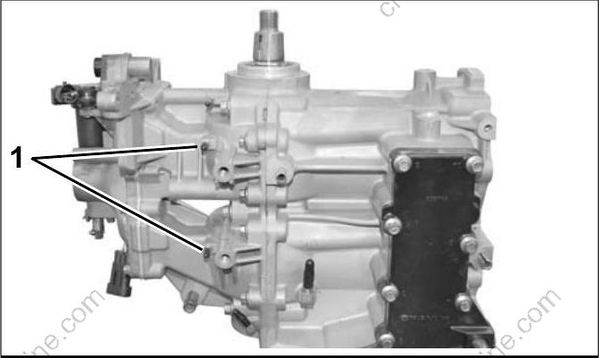
- Crankcase oil fittings
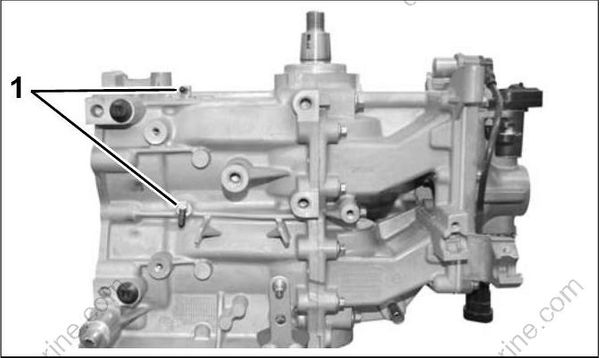
- Cylinder block oil fittings
Oil Recirculation System
External hoses and fittings, and intake manifold passages are used to recirculate any accumulation of oil from various locations in the powerhead. The movement of oil is controlled by check valves.
Crankcase / Main Bearing Recirculation
The movement of oil through the main bearings is controlled by internal passages, external fittings and hoses, and check valves.
Lower to upper main bearing oil flow:
- Lower main bearing cavity to internal crankcase passage to external fitting, external hoses with in-line check valve to external fitting at upper main bearing, and into upper main bearing through internal crankcase passage.
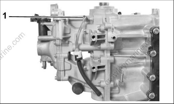
- Upper main bearing vent
Refer to the OIL RECIRCULATION DIAGRAM on p. 144.
