

OIL COMPONENT SERVICING
To prevent accidental starting while servicing, disconnect the battery cables at the battery.
Oil Distribution Hoses
The oil distribution hoses from each manifold MUST be the same length. DO NOT alter the length of any hoses.
| Oil Distribution Hose Length | Oil Distribution Hose Length |
|---|---|
| Primary oil manifold to cylinder block fitting | 12 in. (305 mm) |
| Rear oil manifold to cylinder block fitting | 32 in. (812 mm) |
| Rear oil manifold to primary oil manifold* | 32 in. (812 mm) |
*Rear oil manifold to primary oil manifold hose has a 0.160 in. I.D. and does NOT use a hose support.
Removal
Release the hose by depressing the outer ring of the hose retaining mechanism.
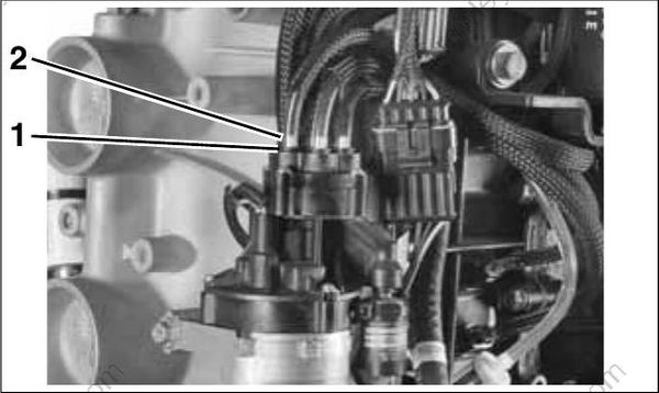
Retainer mechanism
Hose support
Once hose is removed from the manifold, make sure hose support is in the end of the hose.
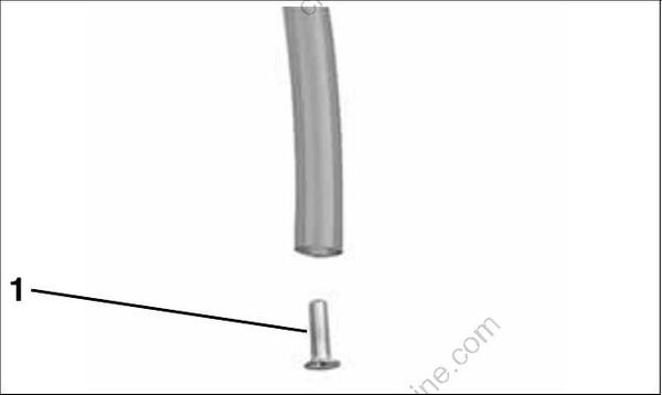
- Hose support
Installation
Cut Replacement Oil Hose, P/N 778708, to the correct length. Insert hose support in manifold end of hose. (Primary manifold to rear manifold hose does not use a hose support.)
IMPORTANT: DO NOT insert distribution hoses into manifold without a hose support.
Be sure the hose is fully inserted into manifold. Insertion depth is 5/8 in. (16 mm). Visually inspect for hose supports.
Oil Injection Pump
Removal
Disconnect the battery cables at the battery. Remove engine cover and air silencer.
Remove the oil supply hose from the fitting (inlet) of the oil injection pump.
Disconnect the electrical connector.
IMPORTANT: Note oil distribution hose routings before proceeding with disassembly. Center hose from primary oil manifold connects to oil to inlet of rear oil manifold.
Remove oil distribution hoses from the crankcase fittings.
Remove oil injection pump screws, bracket, and clamps.
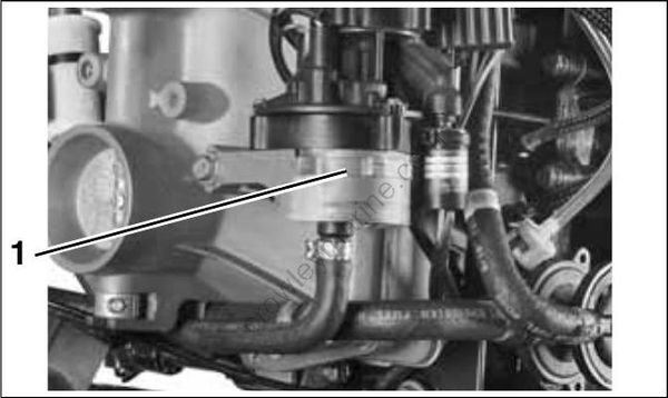
Oil Injector-Manifold Bracket
- Clamp
Remove the oil injection pump assembly.
IMPORTANT: The oil injection pump and manifold is an assembly and cannot be serviced as individual components.
Installation
Route oil distribution hoses from the oil distribution manifold to the crankcase oil delivery fittings as they were before removal. Refer to OIL SUPPLY DIAGRAMS – V4 on p. 196 and OIL SUPPLY DIAGRAMS – V6 on p. 198.
Connect oil hoses to crankcase fittings and fasten with tie straps.
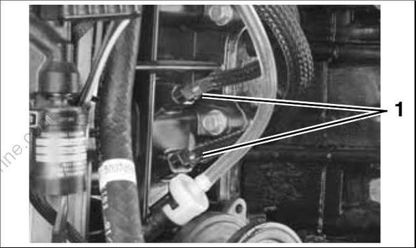
- Crankcase fitting
Connect oil hose to rear oil manifold.
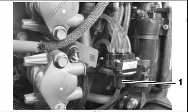
- Oil to rear manifold
Install oil pump bracket and retaining screws. Tighten small screw to a torque of 24 to 36 in. lbs. (3 to 4 N·m) and longer screw to 96 to 120 in. lbs. (11 to 13.5 N·m).
Position the oil injection pump assembly on bracket and install Oetiker clamp.
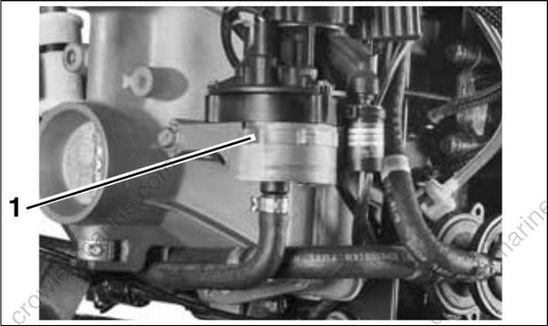
- Clamp
Reconnect the electrical connector.
IMPORTANT: Use oil primer bulb to purge air from oil supply hose before reconnecting hose to oil pump.
Reconnect oil supply hose to the inlet fitting of oil pump. Fasten with Oetiker clamp.
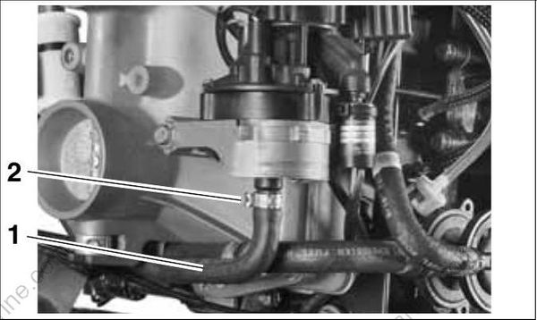
Oil supply hose
Oetiker clamp
Make sure oiling system is primed. Check oil flow through oil distribution hoses. Check oil system operation and routing of oil hoses. Refer to Oil Supply Priming on p. 54.
Run the outboard and check for leaks.
Repair any oil leaks and any kinked or misrouted hoses.
