

Cylinder head
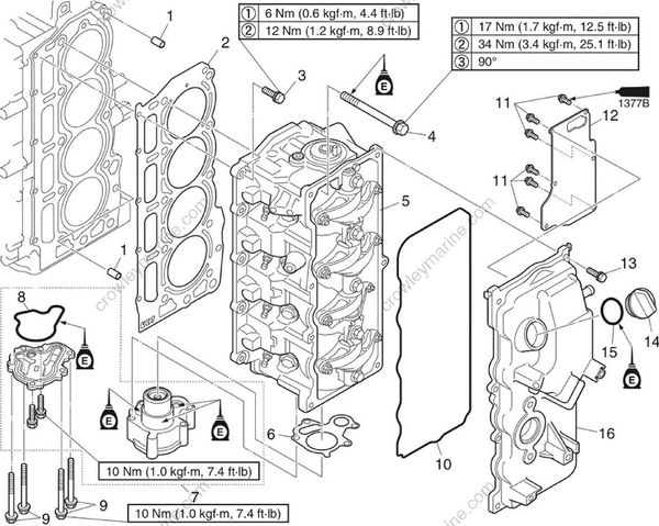
| No | Part name | Q’ty | Remarks |
|---|---|---|---|
| 1 | Dowel pin | 2 | |
| 2 | Gasket | 1 | Not reusable |
| 3 | Bolt | 5 | M6 x 25 mm |
| 4 | Bolt | 10 | M9 x 93 mm |
| 5 | Cylinder head | 1 | |
| 6 | Gasket | 1 | Not reusable |
| 7 | Oil pump assembly | 1 | |
| 8 | Gasket | 1 | Not reusable |
| 9 | Oil pump bolt | 4 | M6 x 45 mm |
| 10 | Gasket | 1 | Not reusable |
| 11 | Screw | 6 | M4 x 10 mm |
| 12 | Plate | 1 | |
| 13 | Bolt | 7 | M6 x 20 mm |
| 14 | Oil filler cap | 1 | |
| 15 | O-ring | 1 | Not reusable |
| 16 | Cylinder head cover | 1 |
Removing the cylinder head
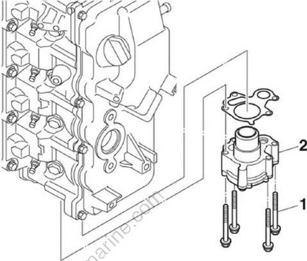
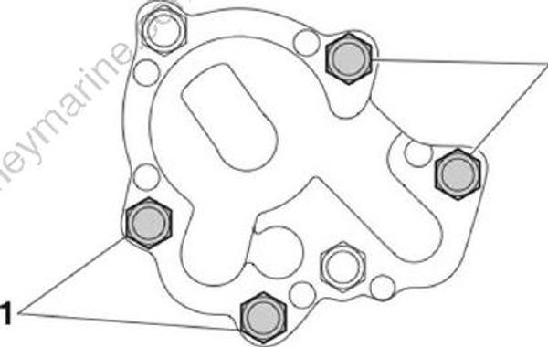
- Remove only the 4 bolts “1” shown in the illustration, and then remove the oil pump assembly “2”.
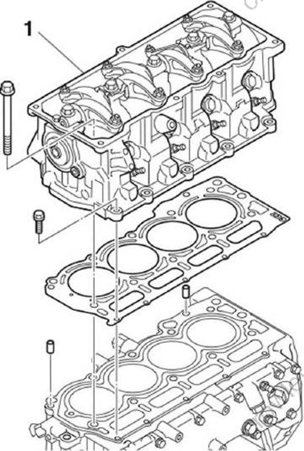
- Remove the cylinder head “1”.
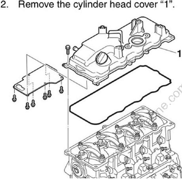
- Remove the cylinder head “1”.
NOTICE: Be careful not to scratch or damage the mating surfaces of the cylinder head and cylinder block.
Disassembling the oil pump
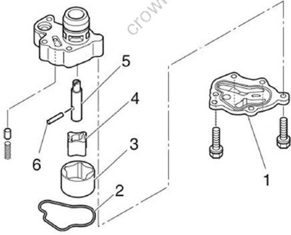
- Remove the oil pump cover “1”, gasket “2”, outer rotor “3”, inner rotor “4”, shaft “5”, and pin “6”.
Checking the oil pump
Check the inner surface of the oil pump housing. Replace the oil pump assembly if scratched.
Check the gear teeth of the inner rotor and outer rotor. Replace the oil pump assembly if the gear teeth are cracked or worn.
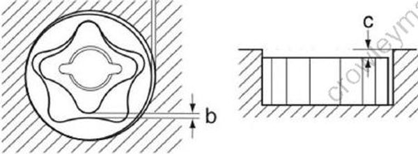
- Measure the oil pump rotor side clearance “a”, tip clearance “b”, and body clearance “c”. Replace the oil pump rotor if out of specification.
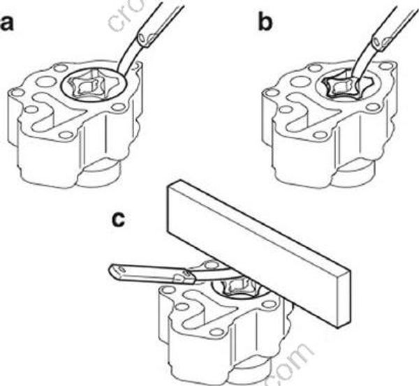
Outer rotor to oil pump housing side clearance “a” (reference data): 0.09 mm (0.0035 in)
Limit (reference data): 0.20 mm (0.0079 in)
Inner rotor to outer rotor tip clearance “b” (reference data): 0.12 mm (0.0047 in)
Limit (reference data): 0.14 mm (0.0055 in)
Body clearance “c” (reference data): 0.08 mm (0.0031 in)
Limit (reference data): 0.13 mm (0.0051 in)
Assembling the oil pump
Install the pin “1 ” to the shaft “2”.
Install the shaft “2”, the inner rotor “3”, the outer rotor “4”, a new gasket “5”, and the oil pump cover “6”, and then tighten the oil pump cover bolts “7” to the specified torque.
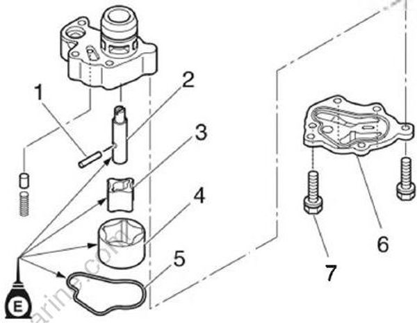
Oil pump cover bolt “7”: 10 Nm (1.0 kgf•m, 7.4 ft•lb)
Checking the cylinder head bolt
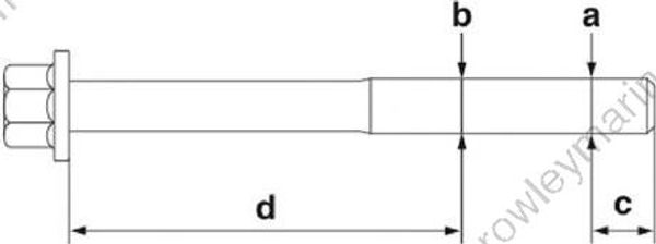
- Measure the diameters “a” and “b” of the cylinder head bolt (M9) at the specified measuring points “c” and “d”. Replace the cylinder head bolt if the difference between the diameters is above specification.
Cylinder head bolt diameter difference limit:
“a” “b” = Less than 0.13 mm (0.0051 in)
Measuring point “c”: 10.0 mm (0.39 in)
Measuring point “d”: 62.5 mm (2.46 in)
Installing the cylinder head
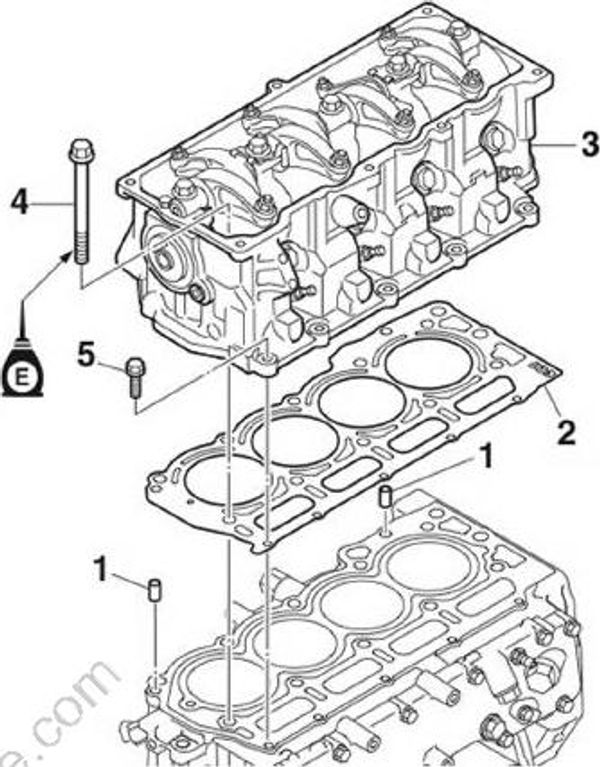
- Install the dowel pins “1”, a new gasket “2”, the cylinder head “3”, and the cylinder head bolts “4” and “5”.
- Tighten the cylinder head bolts “1” to the specified torques in 3 stages and in the order [1], [2], and so on.
3.In the 3rd stage, mark the M9 bolts and cylinder head with paint marks “a”, and then tighten the M9 bolts 90° from the marks on the cylinder head.
- Tighten the cylinder head bolts “2” to the specified torques in 2 stages and in the order [11], [12], and so on.
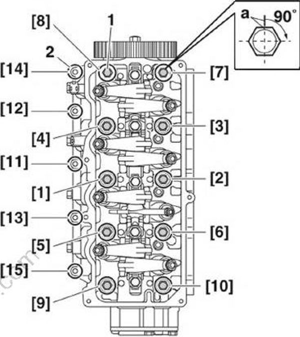
Cylinder head Cylinder head bolt “1” [1 ]-[10] (M9):
1st: 17 Nm (1.7 kgfm, 12.5 ft-lb)
2nd: 34 Nm (3.4 kgf m, 25.1 ft-lb)
3rd: 90°
Cylinder head bolt “2” [11]-[15] (M6):
4th: 6 Nm (0.6 kgf-m, 4.4 ft-lb)
5th: 12 Nm (1.2 kgf m, 8.9 ft-lb)
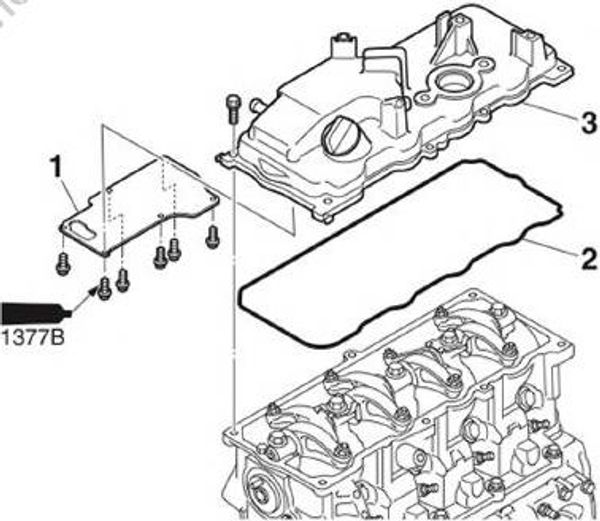
5.Install the plate “1”, a new gasket “2”, and the cylinder head cover “3”.
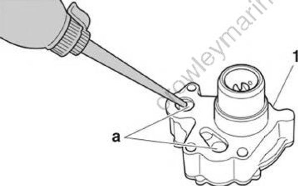
- Fill the oil pump assembly “1” with engine oil through the oil passages “a”.
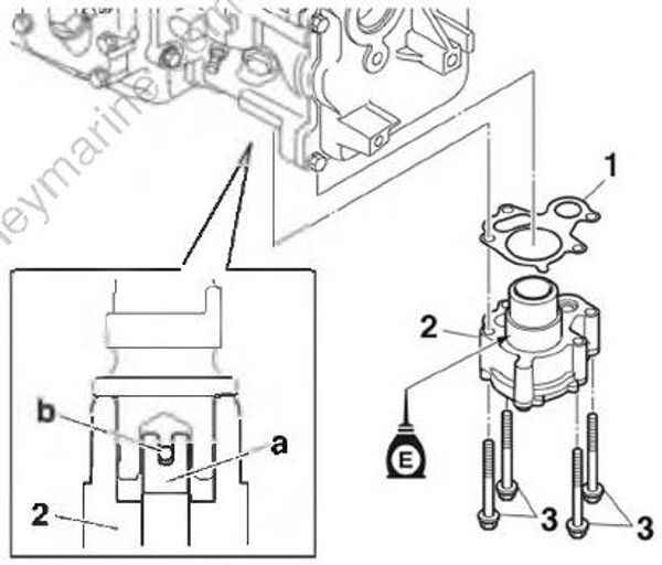
7.Install a new gasket “1”, the oil pump assembly “2”, and the oil pump bolts “3”, aligning the slot in the oil pump drive shaft “a” with the camshaft pin “b”.
- Tighten the oil pump bolts “1” to the specified torque in the order [1], [2], and so on.
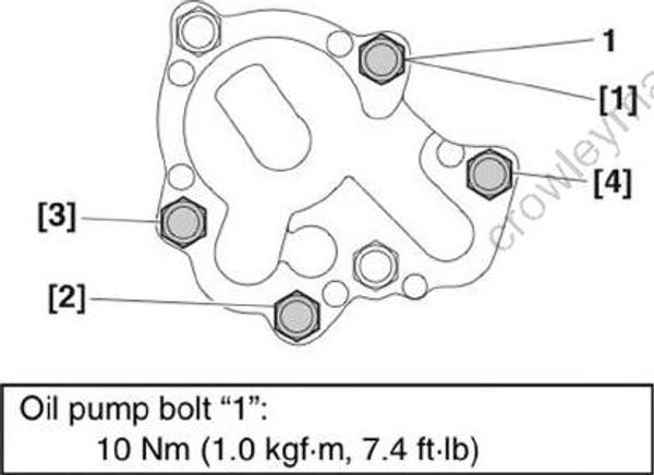
Oil pump bolt "1": 10 Nm ( 1.0 Kgf•m , 7.4 ft•lb)
